


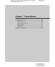
Chapter 7 Frame Memory
C:\WINNT\Profiles\Administrator\Desktop\WORK_08_21\370467401
DVS9000WW\01GB09C07-WW.fm
masterpage:Left
270
Frame Memory Operations
DVS-9000/9000SF
3-704-674-01 (1)
Setting a mask
Masks can be set separately for frame memory source buses 1 and 2. To apply
a mask to the signal selected on frame memory source bus 1, for example, use
the following procedure.
1
In the Frame Memory menu, select VF2 ‘Edit’ and HF6 ‘Input Mask.’
The Edit> Input Mask menu appears.
2
Select the mask source.
[Box Mask1] may be used alone or in combination with [Pattern] or [Ext
Key] in the <Sub Mask1> group.
Box Mask1: Dedicated box generator signal
<Sub Mask1> group
Pattern: Dedicated pattern generator signal
Ext Key: Signal selected on frame memory source bus 2.
The [Ext Key] selection is only possible when [V/K Mode] is
enabled.
3
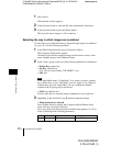
Set the mask source parameters.
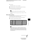
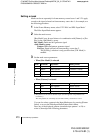
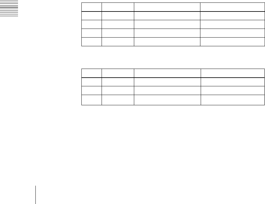
• When [Box Mask1] is selected
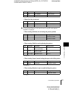
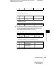
• When [Pattern] is selected
a) The patterns are the same as standard wipes. (See the appendix “Wipe Pattern List”
(Volume 2).)
The same patterns are commonly used on frame memory source buses 1 and 2.
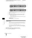
You can also select a pattern in the Input Mask menu, by pressing [Pattern
Select], to access the Edit>Input Mask>Pattern Select menu.
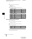
Press any of the displayed patterns (standard wipes pattern 1 to 24) to
select it, then adjust the following parameters.
Knob Parameter Adjustment Setting values
1 Top Top position −100.00 to +100.00
2 Bottom Bottom position −100.00 to +100.00
3 Left Left position −100.00 to +100.00
4 Right Right position −100.00 to +100.00
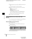
Knob Parameter Adjustment Setting values
1 Size Size of pattern 0.00 to 100.00
2 Soft Edge softness of pattern 0.00 to 100.00
5 Pattern Pattern number
1 to 24
a)