


Chapter 1 Getting Started 1-15
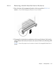
4. Prepare the switch by opening its injector/ejector handles (FIGURE 1-7).
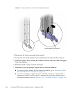
5. Carefully align the edges of the board with the guides in the slot.
Look into the enclosure to verify correct alignment of the rails in the guides.
6. Keeping the board aligned in the guides, slide the board in until the
injector/ejector mechanisms engage the retention bar.
7. Simultaneously push in the board and rotate the injector/ejector handles to their
closed positions (rotate inward) to seat the midplane connectors.
If system power is on, the Hot-Swap LED should light up. The Hot-Swap LED
should blink for several seconds, and then go off. If the Hot-Swap LED does not go
off after several seconds, push harder on the injector/ejector handles to verify that
they are pushed in all the way.
8. Tighten the board retention screws to anchor the board in the shelf.
9. Connect the cables to the switch.
1.9 Switch LEDs
The following sections give the status information for all of the LEDs on the switch.
■ “ATCA Board Status LEDs” on page 1-15
■ “Hot-Swap LED” on page 1-16
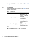
1.9.1 ATCA Board Status LEDs
TABLE 1-3 describes the three LEDs defined by ATCA to monitor board status.
TABLE 1-3 ATCA Board Status LEDs
LED Color Normal Operation Description
OOS Red Off Out of service. This LED lights on a critical switch
error, such that the board should be removed.
OK Green On This LED is lit when the switch is booted and
switching
A Amber Off Minor Error/User Defined. This LED can be defined
by the user via software applicatons.