Appendix C: Options
94
764 Digital Audio Monitor User Manual
Option 02 instruments are set during manufacture for fixed
output; refer to Configuring the Output on page 95 for
information about changing the setting.
When outputting to an unbalanced load (0 to 2.0 V
RMS
variable
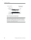
output only), you must connect one of the lines to ground; refer to
Connecting the Instrument on page 97 for more information.
H The analog outputs supercede the digital XLR loop-throughs;
always leave the TERM switches of Option 02 instruments set to
110 W for proper XLR input termination.
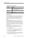
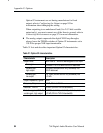
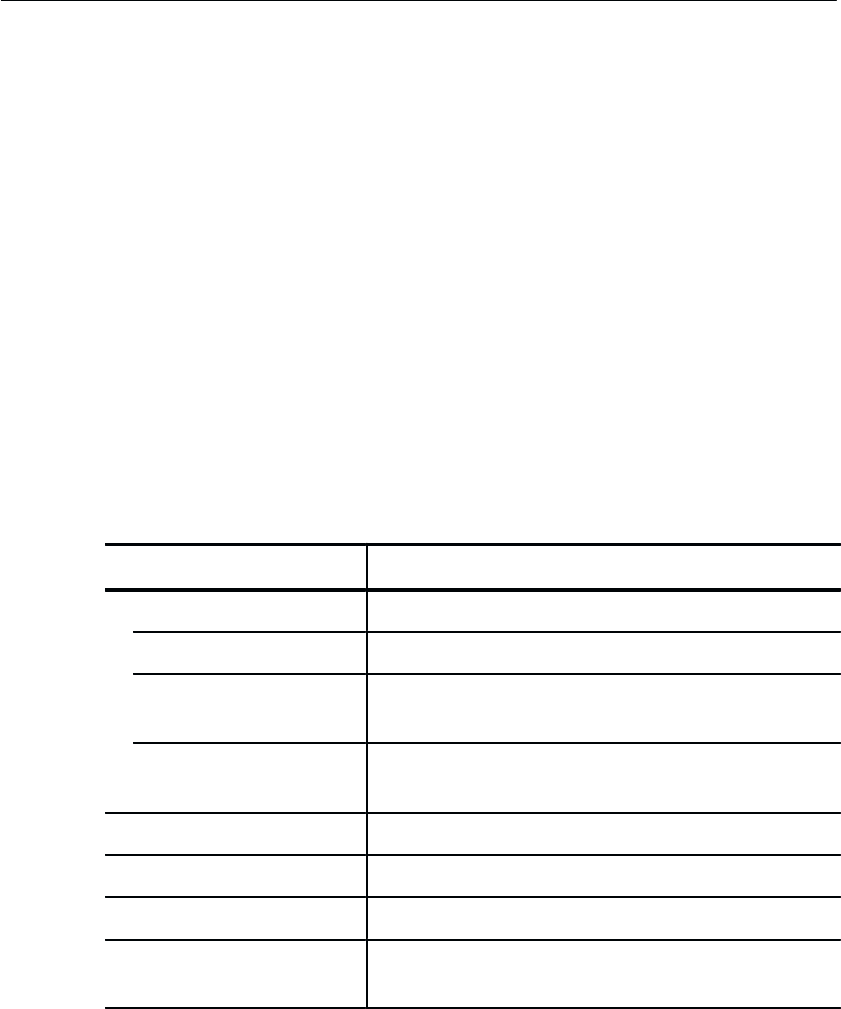
Table 31 lists and describes important Option 02 characteristics.
Table 31: Option 02 characteristics
Characteristic Description
Output Level With 0 dBFS 1 kHz sine wave applied to the input
Fixed gain
+24 dBm +1.6/–0.0 dBm into 600 W balanced
Variable gain,
high output
+24 dBm (volume control fully clockwise) into
600 W balanced
Variable gain,
low output
2.0 V
RMS
(volume control fully clockwise) into
≥10 kW
Output impedance, typical
50 W
Frequency Response ±2 dB, 20 Hz to 20 kHz
Distortion, THD+N <0.05% (22 kHz THD+N bandwidth)
Distortion, typical, THD+N,
variable gain, high output
<0.005% at 1 kHz (control fully clockwise, load
≥10 kW, 22 kHz THD+N bandwidth)


