Getting Started
764 Digital Audio Monitor User Manual
5
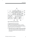
NOTE. The balanced (XLR) loop-throughs are the default 764 inputs.
To receive a signal through the unbalanced (BNC) loop-throughs or
the optional serial video loop-through (Option 01), you must first
reconfigure the instrument through the on-screen menus. Refer to
Initial Power Up and Configuration on page 9 for instructions.
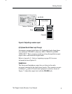
(2) Time Code Inputs
VITC — Reads vertical interval time code from NTSC or PAL analog
video per IEC publication 461 specifications. The time code can be
shown on the SESSION display, and stamped on each error on a
printed Session Report. The format of the Session View time display is
Hours:Minutes:Seconds.
LTC — Reads linear time code that also conforms to IEC specifica-
tions. The time code can be shown on the Session display, and
stamped on each error on a printed Session Report. The format of the
time display is Hours:Minutes:Seconds:Frames.
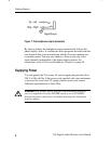
(3) Reference Inputs
Connect your “house” digital audio reference (DAR) signal to one of
the REF IN connectors. These connectors (one BNC, one XLR) accept
the same formats as the Digital Audio Inputs. They are internally
terminated. As with the audio inputs, the default connector is XLR;
use the on-screen menus to select the BNC connector. The 764 can use
any AES signal as a DAR; it will use the reference input to detect and
measure frame synchronization of AES signals.
If you do not connect a house DAR to one of the reference inputs, the
764 will monitor synchronization of the CH 3–4 input signal with the
CH 1–2 input signal. For more information, refer to the explanation of
the Frame Synchronization Error session statistic on page 32.
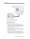
(4) VGA Video Output
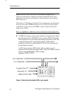
To see a larger, color image of the 764 display (as illustrated in
Figure 5), connect a VGA-compatible monitor to this standard 15-pin
output. Table 25 on page 77 lists the characteristics of the Video
Output signal.


