


Appendix C: Options
764 Digital Audio Monitor User Manual
95
Configuring the Output
Qualified service personnel can change the output configuration with
the following procedure:
CAUTION. The 764 contains static-sensitive components. The
following procedure should be performed by qualified technicians
only.
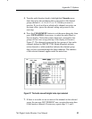
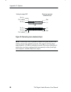
1. Disconnect power and all other connections from the 764 rear
panel and then remove the instrument from its enclosure. The
Analog Line Output circuit board assembly is mounted
horizontally above the audio XLR connectors at the rear of the
chassis. The configuration jumper pins are readily accessible on
the top surface of the board.
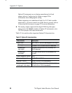
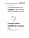
2. Identify the jumper configuration in Table 32 that corresponds to
the desired output; add and remove jumpers to/from the jumper
pin pairs to achieve that configuration. Pin pairs J20, J21, J22,
and J23 are provided as a convenient place to “park” unused
jumpers. If you need additional jumpers for the new configura-
tion, take them from J20–J23; if you have extra jumpers after
reconfiguration, put them onto J20–J23.
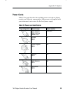
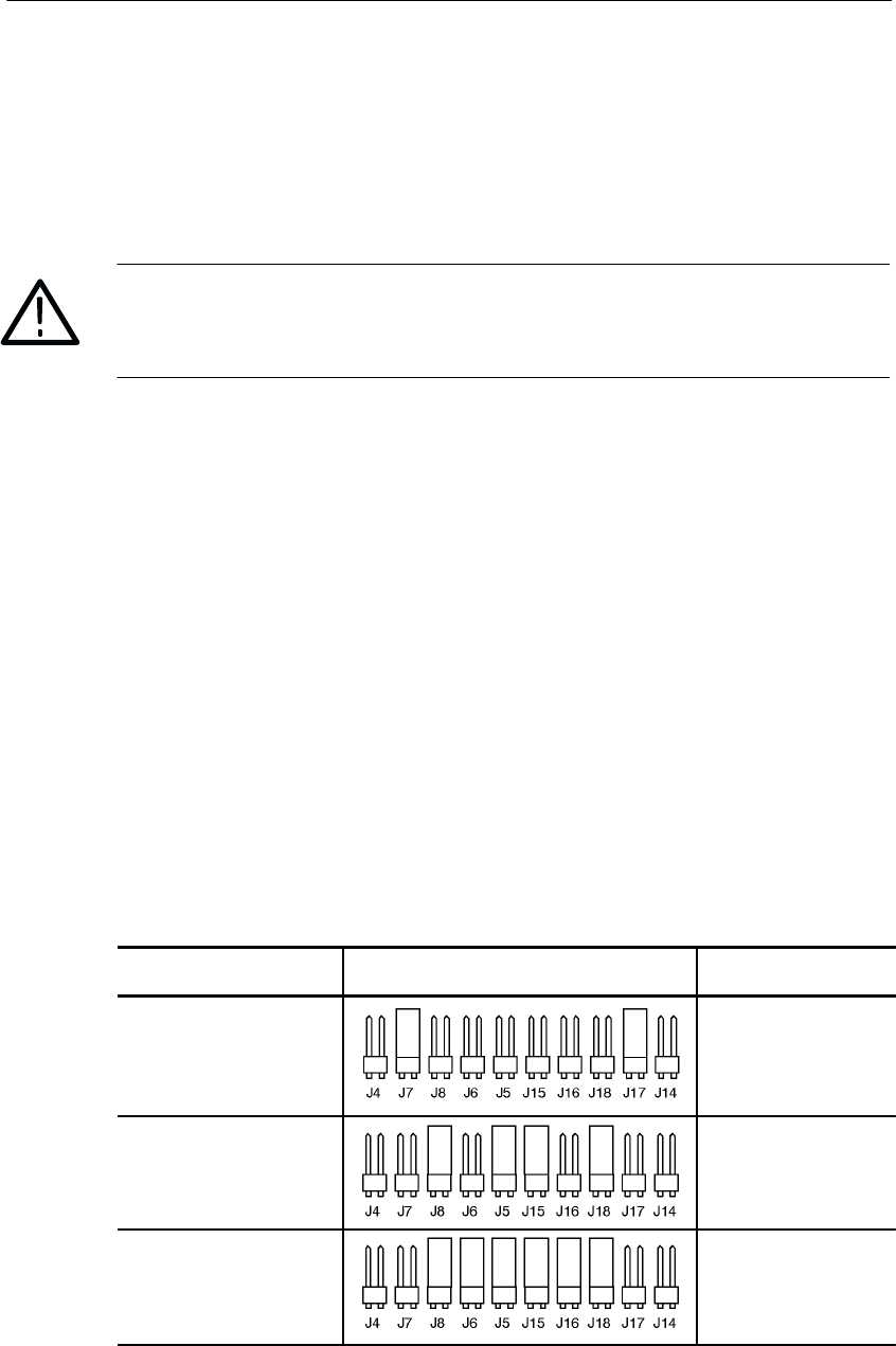
Table 32: Output configuration jumper locations
Output Jumper configuration AES connector*
Fixed, +24 dBm J914
Variable, to +24 dBm J913
Variable, to 2.0V
RMS
J913
* See configuration procedure step 3.