


Appendix C: Options
96
764 Digital Audio Monitor User Manual
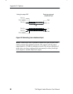
3. Locate J913 and J914, the two rows of six connector pins on the
AES circuit board assembly. The AES board is on the right side
of the 764 when you view the instrument from the rear panel;
J913 and J914 are near the end of the AES board that is closest to
the front of the instrument. The AES–XLR cable must be
connected to either J913 or J914; use J914 for fixed analog audio
output and use J913 for variable output.
If you move the AES–XLR cable, be sure to connect pin one of
the cable connector to pin one on J913 or J914. Pin one is
indicated by a triangular symbol on the circuit board and a
triangular symbol and white dot on the cable connector.
4. Reinstall the 764 in its enclosure and reconnect it to your system.
The appropriate analog audio cable connections depend on the
analog output configuration. Refer to Connecting the Instrument
on page 97 for analog audio cable requirements.
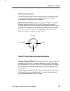
5. The audio input channels routed through the left and right analog
line outputs are the same as on the front-panel headphone output.
During manufacture, the headphone output is set to follow the
phase display. You may manually select the headphone and
analog line output channels through the Headphones submenu;
refer to Selecting Headphone Channels on page 48 for more
information.