


TDS 500C, TDS 600B, & TDS 700C User Manual
3–63
Triggering on Waveforms
To use the TDS Oscilloscope to measure or monitor waveforms, you need to
know how to trigger a stable display of those waveforms. Toward that end, this
section first covers the following topics:
H Trigger Concepts which details some basic principles of triggering and
describes triggering elements: type, source, coupling, holdoff, mode,
and so on
H Triggering from the Front Panel which describes how to use the front-panel
triggering controls each of which is common to most, if not all, the trigger
types the oscilloscope provides
Once these basics are covered, this section describes how to trigger using the
various trigger types provided by the Main trigger system: edge, logic, and pulse.
H To use the “general purpose” trigger type, edge, see Triggering on a
Waveform Edge on page 3–72.
H To logic trigger based on an input pattern, state, or setup/hold violation, see
Triggering Based on Logic on page 3–76.
H To pulse trigger based on various pulse types (glitch, runt) or their parame-
ters (width, slew rate) see Triggering on Pulses on page 3–89.
H To trigger on communication signals (optional on TDS 500C and 700C only)
see Communications Triggering on page 3–103.
This section concludes with details about and instructions for using the Delayed
time base and Delayed trigger system to delay the acquisition of a waveform
relative to a trigger event. (See Delayed Triggering on page 3–106.)
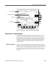
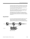
Triggering Concepts
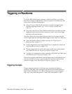
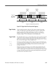
Triggers determine when the oscilloscope stops acquiring and displays a
waveform. They help create meaningful waveforms from unstable jumbles or
blank screens. (See Figure 3–32.) The oscilloscope has five types of triggers:
edge, logic, pulse, and with option 2C, comm, and, with option 05, video.