


Triggering on Waveforms
3–100
TDS 500C, TDS 600B, & TDS 700C User Manual
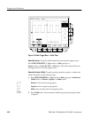
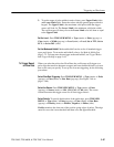
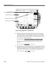
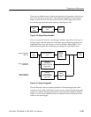
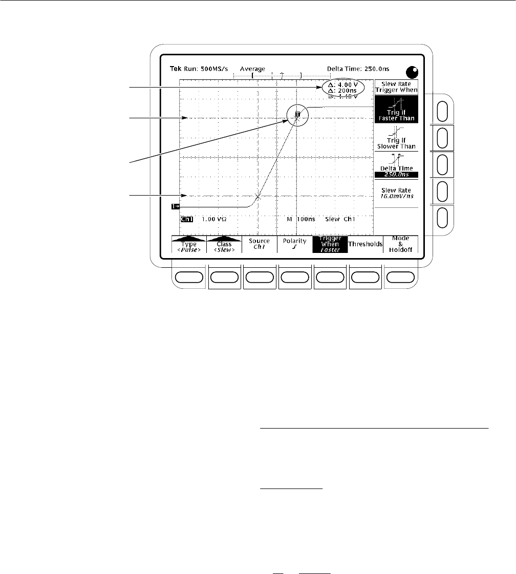
Trigger Bar at Upper Threshold
Trigger Bar at Lower Threshold
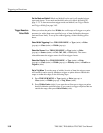
Cursors Measure Slew Rate
Components of Pulse Edge—dv and dt
Trigger Point at Second Crossing
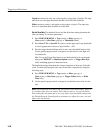
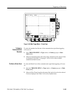
Figure 3–48: Main Trigger Menu — Slew Rate Class
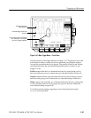
H The Trigger When side menu displays the readout Slew Rate that indicates
the slew rate setting. The slew rate setting is not the slew rate of the pulse;
instead, it is the slew rate against which the oscilloscope compares the slew
rate of pulse (see above). You set the slew rate setting indirectly by setting
the ratio of delta voltage to delta time as:
SlewĂ RateĂ Setting +
UpperĂ ThresholdĂ SettingĂ ćĂ LowerĂ ThresholdĂ Setting
DeltaĂ TimeĂ Setting
Substituting the threshold and delta time settings for the setup in Fig-
ure 3–48:
SlewĂ RateĂ Setting +
4.5Ă VĂ ćĂ 0.5Ă V
250Ă ns
+Ă 16.0Ă mVńns
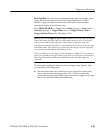
H The trigger bar indicators (long horizontal bars) point to the upper and lower
thresholds. The pair cursors, which are aligned to threshold levels, read out a
delta voltage of approximately 4 V and a delta time of 200 ns between the
threshold levels. Therefore, the slew rate of the pulse edge triggered on is:
SlewĂ RateĂ Measured +
dv
dt
+
4Ă Volts
200Ă ns
+ 20Ă mVńns