


Acquiring and Displaying Waveforms
TDS 500C, TDS 600B, & TDS 700C User Manual
3–7
5. TDS 500C and 700C models only: Press SHIFT ACQUIRE MENU ➞
Mode (main) ➞ Hi Res (side).
6. TDS 600B models only: Press SHIFT ACQUIRE MENU ➞
Mode (main) ➞ Average (side). Use the keypad to set Averages to 5.
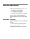
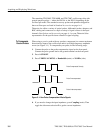
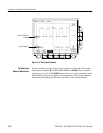
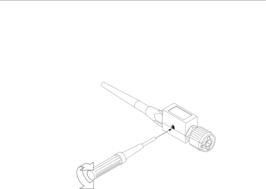
7. Adjust the probe until you see a square wave with a perfectly flat top on the
display. Figure 3–2 shows where the adjustment is located.
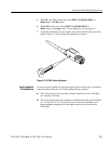
Figure 3–2: P6139A Probe Adjustment
To ensure proper coupling of your input signals to the oscilloscope, consider the
following points when you use 50 W coupling with any channel:
H The oscilloscope does not accurately display frequencies under 200 kHz if
AC coupling is selected.
H The oscilloscope reduces the maximum volts/division setting for the channel
to 1 V from 10 V (to 10 V from 100 V with a X10 probe attached), since
input amplitudes appropriate for the higher settings would overload the
50 W input.
Input Impedance
Considerations