


Tutorial
TDS 500C, TDS 600B, & TDS 700C User Manual
2–19
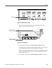
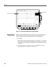
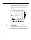
H There are two channel indicators at the left edge of the graticule. Right
now, they overlap.
H The light above the CH 2 button is now on, and the CH 1 light is off.
Because the knobs control only one channel at a time, the vertical
controls are now set to adjust channel 2.
H The trigger readout still indicates that the trigger is detecting trigger
events on channel one. The trigger source is not changed simply by
adding a channel. (You can change the trigger source by using the
TRIGGER MENU button to display the trigger menu.)
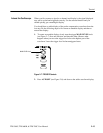
5. Turn the vertical POSITION knob clockwise to move the channel 2
waveform up on the graticule. You will notice that the channel reference
indicator for channel 2 moves with the waveform.
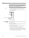
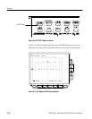
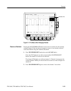
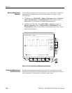
6. Press VERTICAL MENU ➞ Coupling (main).
The VERTICAL MENU button displays a menu that gives you control over
many vertical channel parameters. (See Figure 2–12.) Although there can be
more than one channel displayed, the vertical menu and buttons only adjust
the selected channel.
Each menu item in the Vertical menu displays a side menu. Right now, the
Coupling item in the main menu is highlighted, which means that the side
menu shows the coupling choices. At the top of the side menu, the menu title
shows the channel affected by the menu choices. That channel always
matches the lighted channel button.
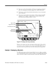
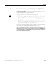
7. Press W (side) to toggle the selection to 50 W. That changes the input
coupling of channel 2 from 1 MW to 50 W. The channel readout for
channel 2 (near the bottom of the graticule) now shows an W indicator
(probes with a level 2 interface automatically select 50 W, but they do not
display W in the readout).