


Using Features for Advanced Applications
TDS 500C, TDS 600B, & TDS 700C User Manual
3–219
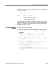
13. Read the following values from the cursor readouts:
H Read the integrated voltage over time between the Xs of both paired
cursors in volt-seconds from the D: readout.
H Read the integrated voltage over time between the X of the selected
cursor and the reference indicator of the math waveform from the @:
readout.
H Read the time difference between the long vertical bars of the paired
cursors from the D: readout.
You can also use automated measurements to measure integral math waveforms.
Use the same procedure as is found under To Take Automated Measurements on
page 3–212. When using that procedure, note that your measurements on an
integral waveform will be in volt-seconds rather than in volts per second as is
indicated for the differential waveform measured in the procedure.
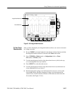
When creating integrated math waveforms from live channel waveforms,
consider the following topics. Note the following requirements for obtaining a
good display:
H You should scale and position the source waveform so it is contained on
screen. (Off screen waveforms may be clipped, which will result in errors in
the integral waveform).
H You can use vertical position and vertical offset to position your source
waveform. The vertical position and vertical offset will not affect your
integral waveform unless you position the source waveform off screen so it
is clipped.
H When using the vertical scale knob to scale the source waveform, note that it
also scales your integral waveform.
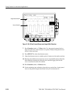
The source waveforms that you connect to the oscilloscope often have a DC
offset component. The oscilloscope integrates this offset along with the time
varying portions of your waveform. Even a few divisions of offset in the source
waveform may be enough to ensure that the integral waveform saturates (clips),
especially with long record lengths.
To Take Automated
Measurements
Offset, Position, and Scale
DC Offset