Using Features for Advanced Applications
3–204
TDS 500C, TDS 600B, & TDS 700C User Manual
H Filter the input to bandwidth limit it to frequencies below that of the Nyquist
frequency.
H Recognize and ignore the aliased frequencies.
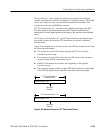
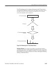
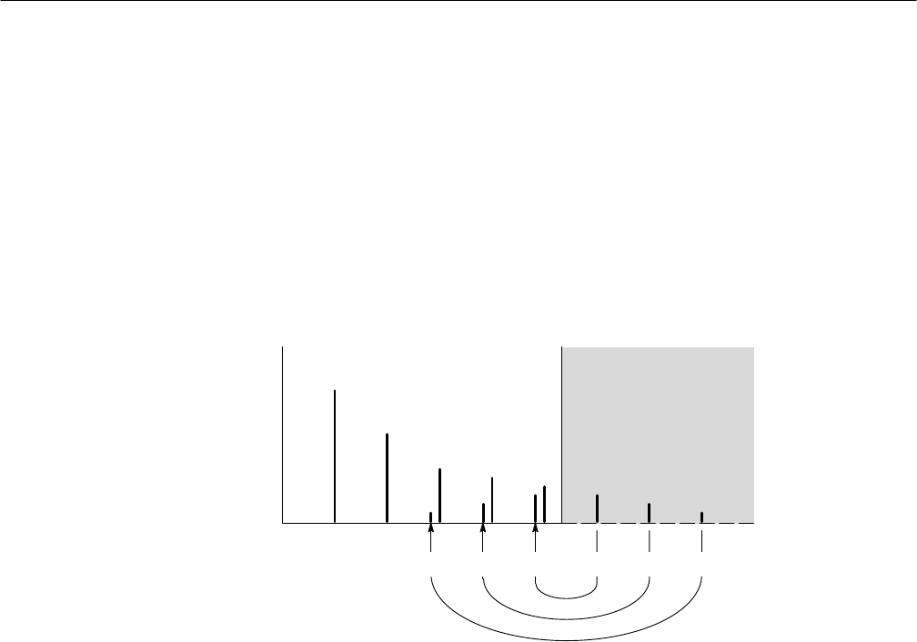
If you think you have aliased frequencies in your FFT, select the source channel
and adjust the horizontal scale to increase the sample rate. Since you increase the
Nyquist frequency as you increase the sample rate, the alias signals should
appear at their proper frequency.
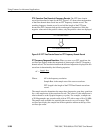
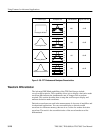
Nyquist Frequency
Point
Frequency
Amplitude
Actual FrequenciesAliased Frequencies
Figure 3–98: How Aliased Frequencies Appear in an FFT
When you set up an FFT math waveform to display the phase angle of the
frequencies contained in a waveform, you should take into account the reference
point the phase is measured against. You may also need to use phase suppression
to reduce noise in your FFTs.
Establish a Zero Phase Reference Point. The phase of each frequency is measured
with respect to the zero phase reference point. The zero reference point is the
point at the center of the FFT math waveform but corresponds to various points
on the source (time domain) record. (See Figure 3–96 on page 3–199.)
Considerations for Phase
Displays


