


4 Replacement Procedures 4.10 Display Assembly
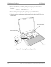
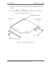
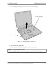
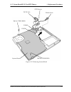
3. Close the display and turn the computer face down.
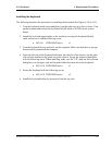
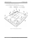
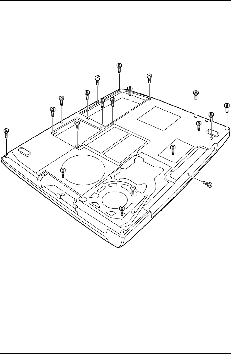
4. Remove the following screws from the bottom and rear of the computer.
• M2.5x5 THIN BIND screw x7 (“5” in the figure)
• M2.5x16 THIN BIND screw x13 (“16” in the figure)
5
5
5
5
5
5
5
16
16
16
16
16
16
16
16
16
16
16
16
16
Figure 4-25 Removing Display Assembly (2)
4-36 Satellite A10/TECRA A1/Satellite Pro A10 Maintenance Manual (960-445)