


3.MAIN UNIT REPLACEMENT
EO18-33016A
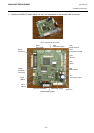
3.2 MAIN PC Board Ass’y
3- 4
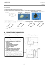
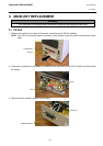
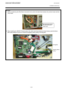
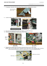
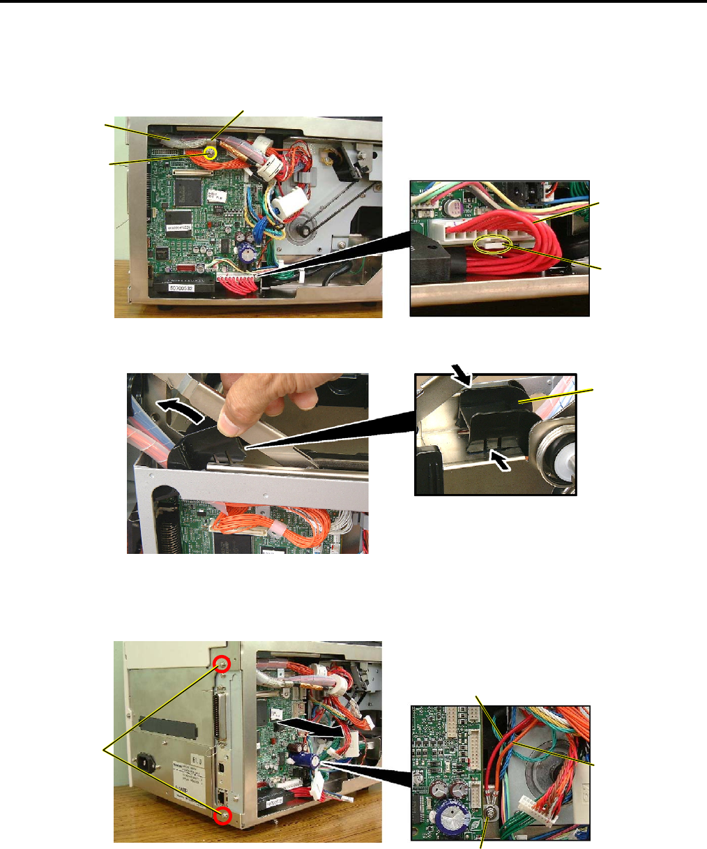
6. Remove the screw to detach the Cable Clamp fixing the Print Head Cable (white).
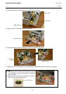
7. Disconnect the all cables from the MAIN PC Board ass’y.
NOTE: Be careful that the connector of the Power Cable has a connector lock.
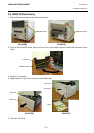
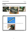
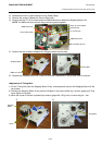
8. To easily remove the MAIN PC board from the B-SA4TM model, remove the cable protection cover by
squeezing and raising it.
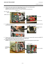
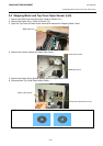
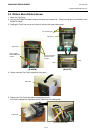
9. Remove the two screws from the printer back. Also, remove the screw which secures the MAIN PC
board together with the ground wires (orange and red lead wires).
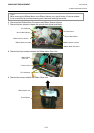
10. Remove the MAIN PC board Ass’y from the printer.
NOTE: Be careful not to hit the component parts on the MAIN PC board against the printer frame.
Cable Clamp
Print Head Cable
(
White
)
SMW-3x8 Screw
Power Cable
Connector Lock
P-3x6 Screw
and Toothed
Washer
SMW-3x6 Screw
Cable Protection
Cover
Orange Lead Wire
Red Lead Wire