


177
Data Ports
Serial Data Port
9/6/07 XiIIIPlus/R110Xi/R170Xi User Guide 13383L-004 Rev. A
Pin Configuration
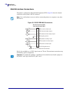
Connect the serial data cable to the female DB-9 connector on the back of the printer. For all
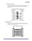
RS-232 connections through a DB-25 cable, use a DB-9 to DB-25 interface module (see DB-9
to DB-25 Connections on page 179).
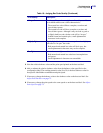
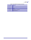
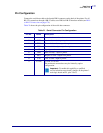
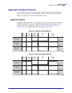
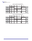
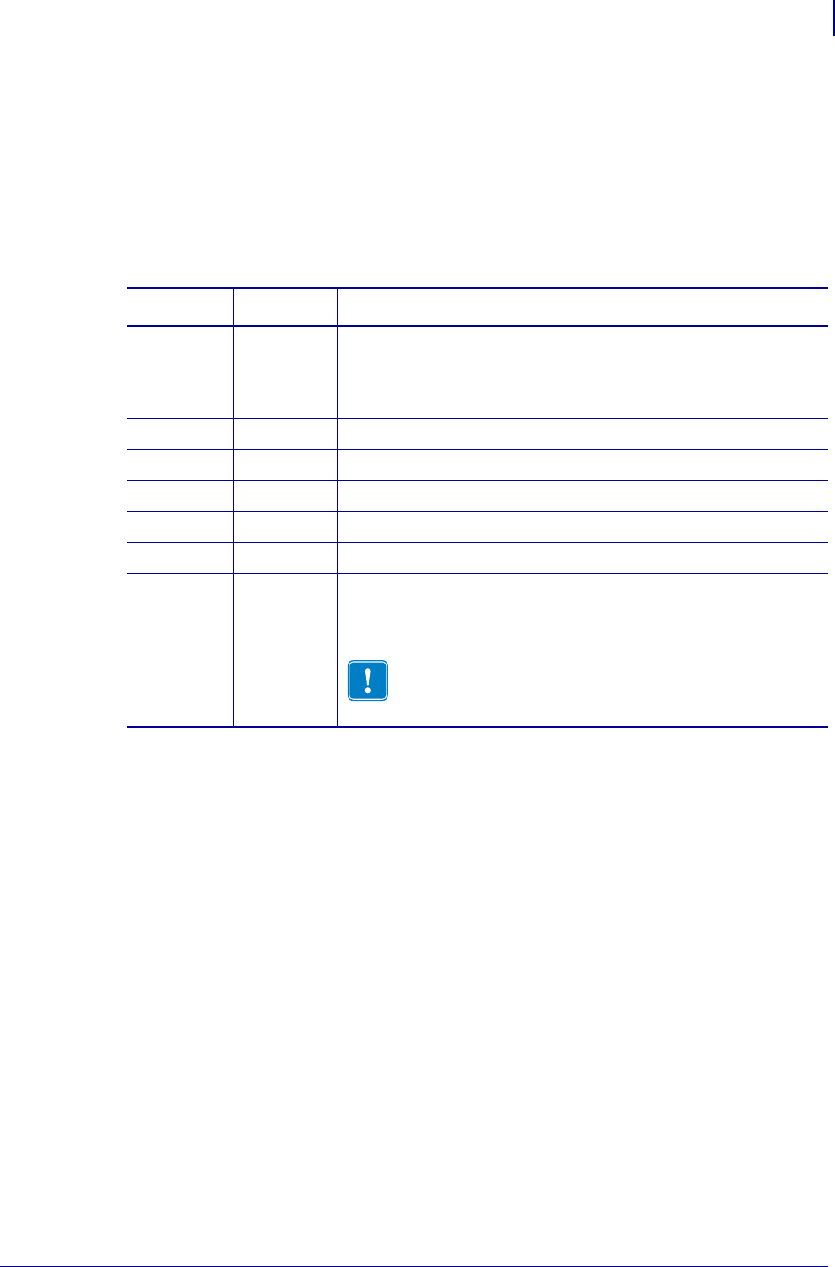
Table 21 shows the pin configuration of the serial data connector.
Table 21 • Serial Connector Pin Configuration
Pin No. Name
Description
1 – Unused and unterminated
2 RXD Receive data—data input to printer
3 TXD Transmit data—data output from printer
4 DTR Data terminal ready—output from printer
5 SG Signal ground
6 DSR Data set ready—input to printer
7 RTS Request to send—output from printer
8 CTS Clear to send—input to printer
9 +5 VDC +5 VDC at 750 mA
The maximum current draw may be limited by option
configuration.
Important • To enable this capability, a qualified
service technician must install a jumper on the printer’s
main logic board on JP1, pins 2 and 3.