


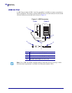
Data Ports
Applicator Interface Connector
186
13383L-004 Rev. A XiIIIPlus/R110Xi/R170Xi User Guide 9/6/07
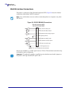
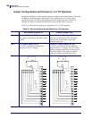
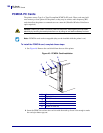
Jumper Configurations and Pinouts for +5 V I/O Operation
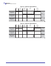
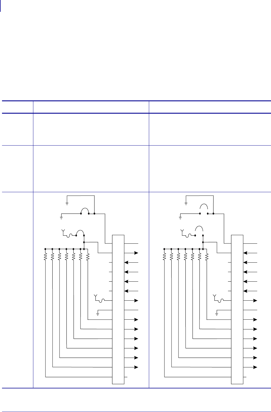
Jumpers JP1 and JP2 are used together to produce isolated or non-isolated modes of operation
for applicator input and output control signals. JP1 configures the +5 V source for the
optoisolator circuits, and JP2 configures the ground. For proper operation, when JP1 is
installed, JP2 must be installed, and when JP1 is removed, JP2 must be removed.
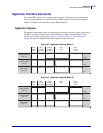
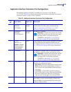
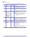
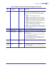
Table 23 describes the pin and jumper configurations for +5 V I/O operation.
Table 23 • Non-Isolated and Isolated Modes for +5V Operation
Non-Isolated (Jumpers In) Isolated (Jumpers Out)
Pin 1 Ground +5V, Jumper JP2 In
I/O ground is connected to the printer signal
ground.
External Ground +5V, Jumper JP2 Out
I/O ground is disconnected from the printer
signal ground. Ground must be provided
externally to this pin.
Pin 2 +5V Output, Jumper JP1 In
+5 V I/O is connected to the applicator
interface circuit +5 V Supply.
External +5V Input, Jumper JP1 Out
+5 V I/O is disconnected from the applicator
interface circuit +5 V Supply. The +5 V for the
applicator interface optoisolator circuits must be
provided externally. This input also supplies
voltage for output signal pull-up resistors.
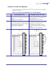
Pinouts
2
3
4
5
6
7
8
9
1
10
10
11
11
12
12
13
13
14
14
15
15
+5V
JP1
JP2
1A
+5V +5V
+28V
+28V
2A
2
3
4
5
6
7
8
9
1
10
10
11
11
12
12
13
13
14
14
15
15
JP1
JP2
+5V
1A
+5V
+28V
+28V
+5V
2A