


185
Data Ports
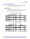
Applicator Interface Connector
9/6/07 XiIIIPlus/R110Xi/R170Xi User Guide 13383L-004 Rev. A
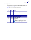
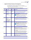
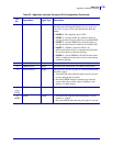
11 END PRINT Output See Applicator Signals on page 181 for more information
about the start and end print signals. See Set Applicator
Port Mode on page 95 for more information about the
modes.
• MODE 0—The applicator port is OFF.
• MODE 1—Asserted LOW only while the printer is
moving the label forward; otherwise deasserted HIGH.
• MODE 2—Asserted HIGH only while the printer is
moving the label forward; otherwise deasserted LOW.
• MODE 3—(Default) Asserted LOW for 20
milliseconds when a label is completed and positioned.
Not asserted during continuous printing.
• MODE 4—Asserted HIGH for 20 milliseconds when a
label is completed and positioned. Not asserted during
continuous printing.
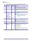
12 MEDIA OUT Output Asserted LOW while there is no media in the printer.
13 RIBBON OUT Output Asserted LOW while there is no ribbon in the printer.
14 DATA READY Output See Applicator Signals on page 181 for more information
about this signal.
• Asserted LOW when sufficient data has been received
to begin printing the next label.
• Deasserted HIGH whenever printing stops after the
current label, due to either a pause condition or the
absence of a label format.
15
(Non-
RFID)
SPARE Output To be determined.
15
(RFID)
VOID Output • Asserted LOW when the RFID transponder over the
antenna is “voided.”
• Deasserted HIGH when the end print signal is asserted.
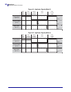
Table 22 • Applicator Interface Connector Pin Configuration (Continued)
Pin
No.
Signal Name Signal Type Description
* Applicator boards have separate part numbers for the +5V version (49872-099M) and the +24-28V version (33361-099M).