


30 C
HAPTER
3: I
NSTALLING
M
EDIA
M
ODULES
5
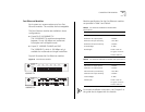
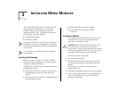
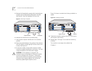
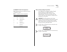
Remove the faceplate by grasping the injector/ejector
handles and simultaneously rolling them outward.
See Figure 9. Save the faceplate for future use.
Figure 9
Removing a Faceplate
6
Remove the module from its antistatic bag.
7
Verify that the injector handles are in the outward
position.
8
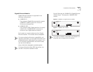
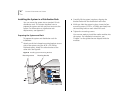
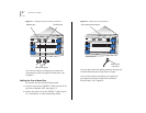
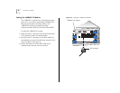
Place the module between the guides of the selected
slot and slide the module gently into the chassis until
it stops. See Figure 10.
9
To seat the module, firmly roll the injector handles
inward to engage the backplane connectors. You feel
a slight resistance as the connectors engage.
CAUTION: If the resistance is too great, the
connectors may not be aligned. Forcing the module
inward can damage the connectors. If necessary,
remove and reinsert the module, ensuring that the
connectors are properly aligned. Do not seat the
module by tightening the captive screws.
Figure 10 shows a module that is being installed in a
system.
Figure 10
Installing a Module
10
Tighten the module’s captive screws to firmly secure
the module in the chassis.
11
Repeat steps 1 through 10 to install the remaining
modules.
The module is now ready to be cabled. See
Chapter 4.
RUN SYS
INS
PS1
PS2
FAN
R
N
S
TEMPCONFIG
INS
PCMCI
MODEM
TERMINAL
ETHERNET
10BT
PWR
ERROR
R
Captive screw
Faceplate
RUN SYS
INS
PS1
PS2
FAN
R
N
S
TEMPCONFIG
INS
PCMCI
MODEM
TERMINAL
ETHERNET
10BT
PWR
ERROR
1X
L E T
2X
L E T
3X
L E T
4X
L E T
5X
L E T
6X
L E T
100 BASE - TX
3C35210
PWR
INS
ERR
R
Captive screw Module