


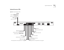
System Checks 51
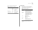
Table 11 summarizes the module LED activity.
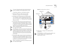
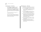
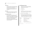
System Checks
After the system has successfully completed the
power-up diagnostics, check the items in Table 12 to
verify that the system is operating correctly.
.
If you discover any abnormal conditions, see
Chapter 7.
Table 11
Module Diagnostics — LED Activity
LED Name Color Indicates
ERR
(Error - Module)
Steady
yellow
Diagnostics failed.
Blinking
yellow
A hardware/software
mismatch has
occurred.
E
(Error - Port)
Yellow Port not operational.
L
(Link status - Port)
Green Diagnostics successful.
T
(Traffic status - Port)
Green Port is receiving or
transmitting data.
Tab le 1 2
System Power-up Checklist
Check Why?
Power-up error
messages
If the software finds a problem during
power up, messages are displayed in the
Administration Console connection
through the terminal serial port.
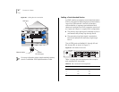
Normal LED
activity
When the power-up diagnostics are
running, the LEDs light in the pattern
described on page 48 in the section
“Power-up Diagnostics.” After the system
successfully completes the power-up
diagnostics, check for the following
normal LED activity:
System
PWR
LED = green
RUN
LED = blinking green
SYS
LEDs = off
Module
ERR
LED = off
Ports
L
LEDs (Link port status) = green
E
LEDs (Error port status) = off
T
LEDs (Traffic port status) = flashing green