


Fan Tray Assembly Removal and Replacement 75
7 Tighten the captive screws that secure the power
supply to the chassis.
8 Lift the power supply latch and insert the power cord
into the system.
9 Insert the other end of the power cord into the
building’s power outlet.
If your system has two power supplies, be sure to
connect the second power supply. Leaving the second
power supply installed but not connected to the
power outlet causes the system diagnostics to
generate a power supply error.
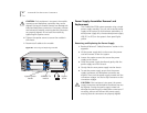
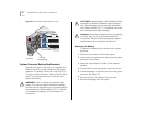
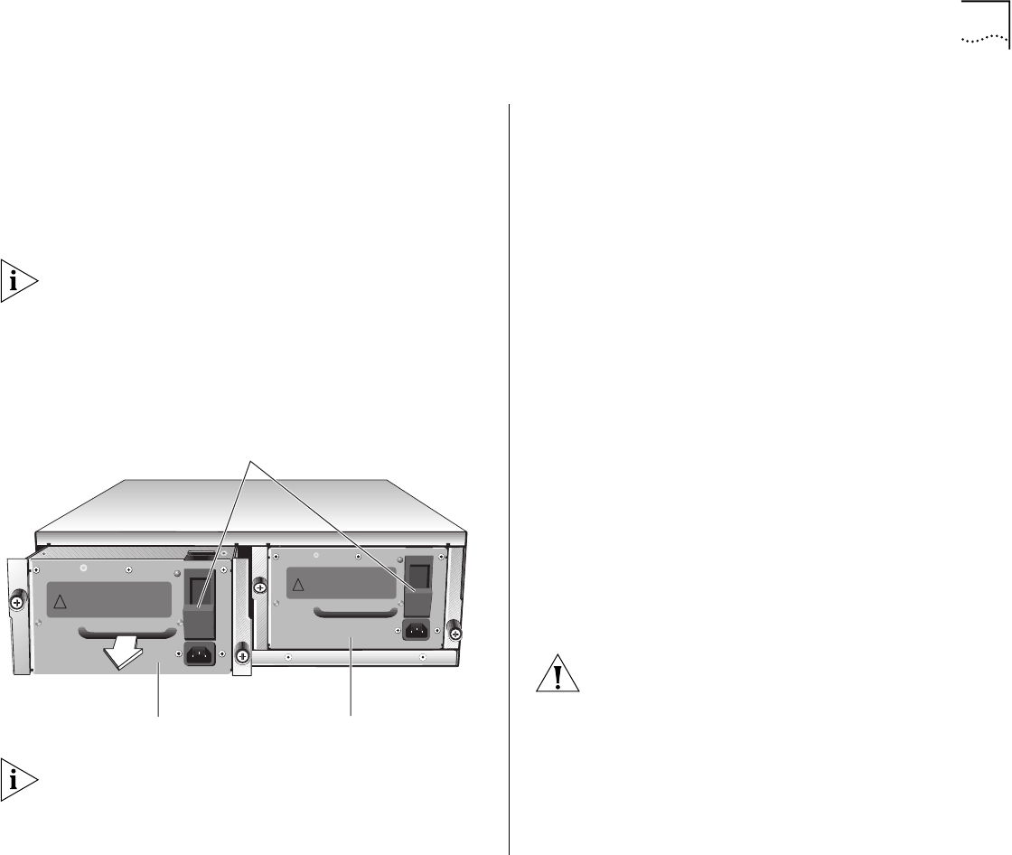
Figure 27
Removing and Replacing the Power Supplies
The power supply LED on the system processor lights
green when the related power supply is operating
properly.
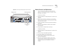
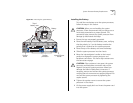
Fan Tray Assembly Removal and Replacement
The system processor and modules are cooled by the
fan tray assembly, which contains two 12-volt DC
fans. The fans are thermally controlled, which means
that they run at slower speeds when the system is
operating at temperatures of less than 30 °C (86 °F)
and at full speed when the system temperature is
above that.
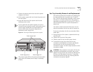
You need no tools to remove the fan tray. You can
remove and replace the fan tray with the power on.
To remove and replace the fan tray assembly, follow
these steps:
1 Facing the front of the system, squeeze the fan tray
mounting tab.
2 Slide the fan tray out of the system.
3 Slide the new fan tray into the system chassis.
4 To seat the fan tray, ensure that the fan tray
connectors and backplane connectors are aligned,
and then push the fan tray inward until the
connectors engage. You feel a slight resistance as the
connectors engage.
CAUTION:
If the resistance is too great, the fan tray
connectors and backplane connectors may not be
aligned. Forcing the fan tray inward can damage the
fan tray or the backplane connectors. If necessary,
remove and reinsert the fan tray, ensuring that the
connectors are properly aligned.
DC OK
!
DC OK
!
Power Supply No. 2
Power Supply No. 1
Power supply latch