


4
C
ABLING
This chapter describes how to cable your
CoreBuilder
®
3500 system for connecting these
elements to your network:
■ System processor ports
■ Fast Ethernet modules
■ Gigabit Ethernet modules
■ FDDI modules
When all your Fast Ethernet, Gigabit Ethernet, FDDI,
and system network connections are complete, see
Chapter 5.
If you are staging the system, you do not need to
connect it to the network yet. However, to view
possible error messages while the system is running
power-up diagnostics, you do need to connect a
terminal, a workstation, or a PC with terminal
emulation to the system’s terminal port. See
Chapter 6.
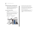
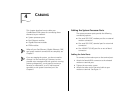
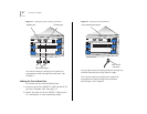
Cabling the System Processor Ports
The system processor ports provide the following
connectivity options:
■ One serial (RS-232C) modem port for an external
modem connection
■ One serial (RS-232C) terminal port for a terminal
connection
■ One 10BASE-T (RJ-45) port for an out-of-band
connection
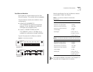
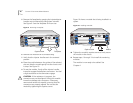
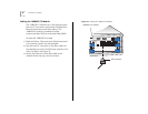
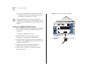
Cabling the Serial Ports
To connect to the modem port or the terminal port:
1
Attach the female DB-9 connector to the selected
modem or terminal port.
2
Tighten the connector screws.
3
Attach the other end of the serial cable to your
modem or terminal. See Figure 11.