


Cabling FDDI Modules 45
For more information about dual-attached stations,
see the
CoreBuilder 3500 Implementation Guide
.
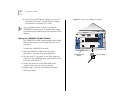
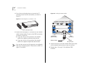
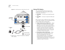
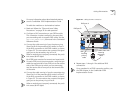
To cable the module as a dual-attached station:
1 Read and follow the “Fiber and Laser Safety
Precautions” on page 35 for safe operation.
2 Configure a DAS connection on your FDDI module.
This connection involves configuring the ports that
you are working with to support DAS mode. See the
fddi stationMode modify command in the
Command
Reference Guide
.
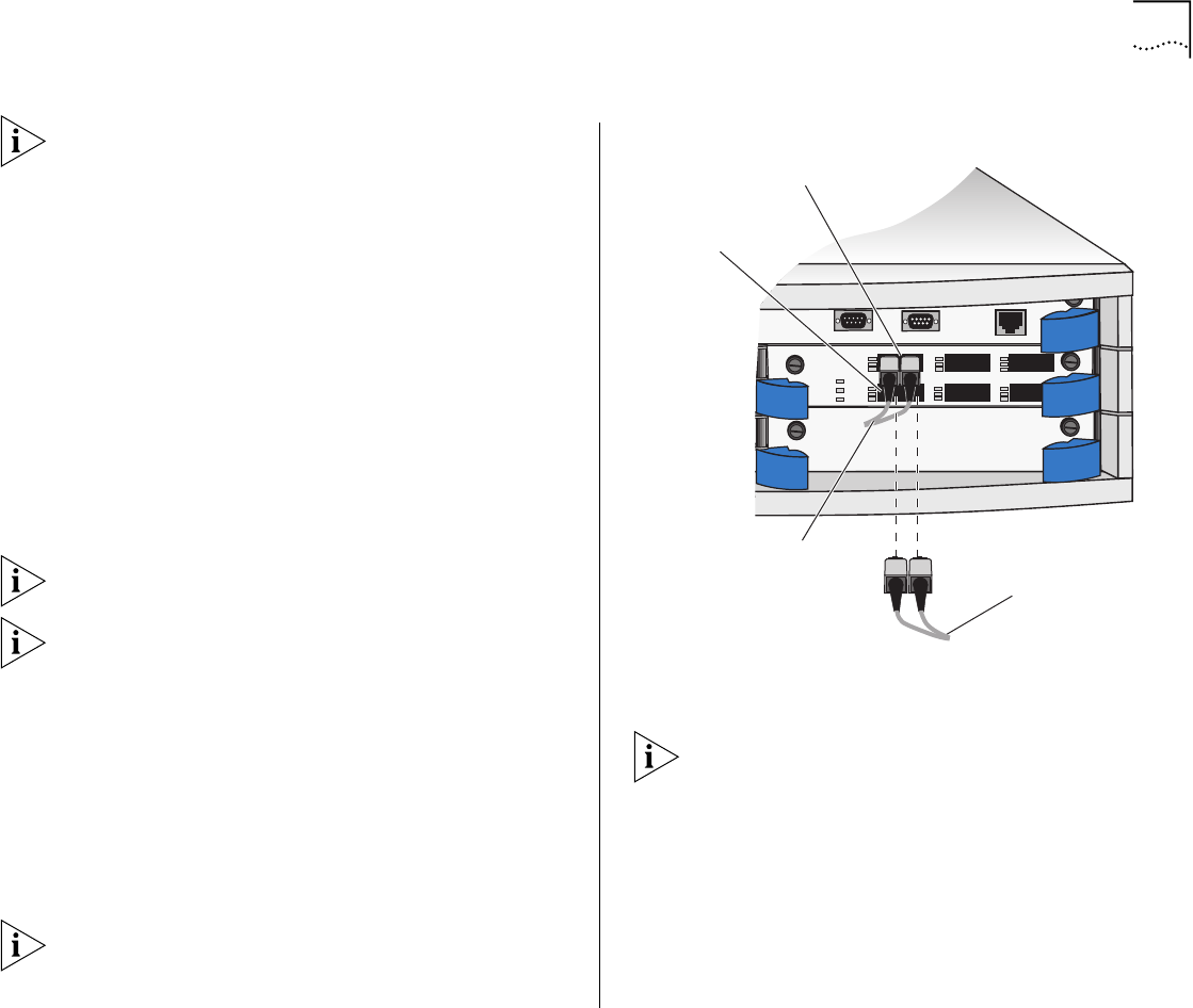
3 Connect the cable coming in from the primary ring
(from Port B of the preceding DAS station) to Port A
of the DAS connection on the FDDI module, as shown
in Figure 22. This connection also connects the signal
going out to the secondary ring to Port A.
When a module port is properly connected, the port’s
Link status (
L
) LED lights.
Each FDDI port consists of a transmit and receive side.
For each FDDI port-to-port connection, verify that you
cable the transmit side of one FDDI port to the receive
side of the FDDI port to which you are connecting;
and the receive side of one port to the transmit side
of the other.
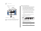
4 Connect the cable coming in from the secondary ring
(from Port A of the preceding DAS station) to Port B
of the DAS connection on the FDDI module, as shown
in Figure 22. This connection also connects the signal
going out to the primary ring to Port B.
When a module port is properly connected, the port’s
Link status (
L
) LED lights.
Figure 22
Cabling the DAS Connection
5 Repeat steps 1 through 4 for additional DAS
connections.
For a complete list of FDDI connection policies, see
the FDDI chapter in
the
CoreBuilder 3500
Implementation Guide.
C
100 BASE - FX
3C54321
PWR
INS
ERR
1X
L
E
T
2X
L
E
T
3X
L
E
T
6X
L
E
T
5X
L
E
T
4X
L
E
T
INS
MODEM
TERMINAL
ETHERNET
10BT
DAS port A
DAS port B
Incoming
primary
cable
Incoming
secondary
cable