


72 A
PPENDIX
B: F
IELD
-R
EPLACEABLE
C
OMPONENTS
ESD Safety Information
Electrostatic discharge (ESD) can damage components
on the system processor board or on a module. ESD,
which occurs when the board is improperly handled,
can cause intermittent failures. To prevent ESD-related
damage:
■
Always wear an ESD wrist strap, ensuring that it
makes good skin contact and is attached to a
proper ground.
■
Keep the board in its antistatic shielded bag until
you are ready to install it.
■
Always handle the board by its edges.
■
Do not touch the components, pins, leads, or
solder connections.
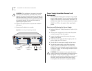
System Processor Removal and Replacement
3Com recommends that you remove the power cord
from the system when you replace the system
processor. To remove and replace the processor:
1
Read and follow all “Safety Precautions” earlier in this
appendix.
2
Disconnect the power cord from the power
receptacle.
3
Record their positions and then disconnect all cables
attached to the system processor.
4
Loosen the two captive screws that secure the system
processor in the chassis.
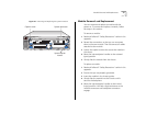
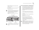
5
Move the injector/ejector handles to the outward
(eject) position. See Figure 25.
6
Gently slide the system processor out of the chassis.
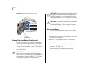
To replace the system processor:
1
Ensure that you are properly grounded.
2
Insert the new system processor in the chassis guides.
3
Gently slide the processor into the chassis until it
touches the backplane.
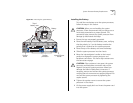
4
Move the injector/ejector handles to the inward
(inject) position. You feel a slight resistance as the
system processor connectors and backplane
connectors engage.
CAUTION: If the resistance is too great, the system
processor connectors and backplane connectors may
not be aligned. Forcing the system processor inward
can damage the board and backplane connectors. If
necessary, remove and reinsert the system processor,
ensuring that the connectors are properly aligned. Do
not seat the system processor by tightening the
captive screws.
5
Tighten the captive screws to secure the system
processor in the chassis.
6
Reconnect all cables to the system processor.
7
Lift the power supply latch and insert the power cord
into the system.
8
Insert the other end of the power cord into the
building’s power outlet.