


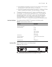
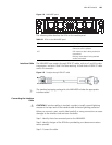

MIM-4BSE Module 103
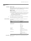
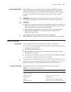
Figure 114 MIM-4BSE panel
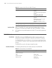
The following table describes the LEDs on the module panel.
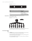
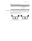
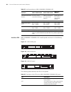
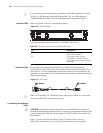
Interface Cable The MIM-4BSE uses straight-through ISDN S/T cables, with pins 3 and 6 for data
transmission, and pins 4 and 5 for data receiving. At both ends of ISDN S/T cable
are RJ-45 connectors.
Figure 115 Straight-through ISDN S/T cable
n
The standard equipping package for the MIM-4BSE includes the appropriate
interface cables.
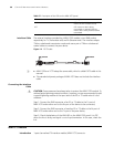
Connecting the Interface
Cable
c
CAUTION: If outdoor cabling is involved, consider to install a special lightning
arrester at the input end of the interface cable for better lightning protection.
Before you connect a port, read its label carefully; a wrong connection can cause
damages to the interface card and even the device.
Step 1: Identify the to-be-connected port on the MIM-4BSE.
Step 2: Identify the type of the ISDN line provided by your telecommunications
service provider.
Step 3: Connect the cable.
Table 62 LEDs on the MIM-4BSE panel
LED Description
LINK OFF means no link is present.
ON means a link is present.
ACT OFF means no data is being received or
transmitted.
Blinking means data is being received
and/or transmitted.
Green
Yellow
Red
Black
Yellow
Green
Black
Red
Green
Yellow
Red
Black
Yellow
Green
Black
Red
Green
Yellow
Red
Black
Yellow
Green
Black
Red
Green
Yellow
Red
Black
Yellow
Green
Black
Red