


FIC-2BSV/FIC-4BSV Module 223
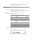
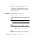
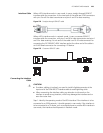
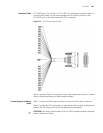
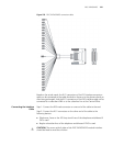
Interface Cable When a BSV interface works in user mode, it uses a straight-through ISDN S/T
interface cable for connection. At the two ends of the cable are RJ-45 connectors
with pins 3 and 6 for data transmission and pins 4 and 5 for data receiving.
Figure 274 Straight-through ISDN S/T cable
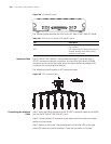
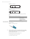
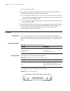
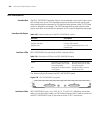
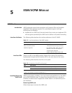
When a BSV interface works in network mode, it uses a crossover ISDN S/T
interface cable for connection, with pins 3 and 6 for data transmission and pins 4
and 5 for data receiving. At one end of the cable is an RJ-45 male connector for
connecting the FIC-2BSV/FIC-4BSV interface and at the other end of the cable is
an RJ-45 female connector for connecting a TE device.
Figure 275 Crossover ISDN S/T cable
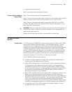
Connecting the Interface
Cable
c
CAUTION:
■ If outdoor cabling is involved, you need to install a lightning arrester at the
input end of the ISDN BRI S/T interface cable to avoid lightning strike.
■ When connecting the interface cable, pay attention to the mark on the
interface to avoid wrong insertion, which may damage the interface card or
even the router host.
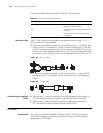
Step 1: Identify the operating mode of the BSV interface. If the interface is to be
connected to an ISDN network, it should operate in user mode; if the interface is
to be connected to a TE device, such as a digital phone or another BSV interface in
user mode, the interface should operate in network mode.
Green
Yellow
Red
Black
Yellow
Green
Black
Red
Green
Yellow
Red
Black
Yellow
Green
Black
Red
Green
Yellow
Red
Black
Yellow
Green
Black
Red
Green
Yellow
Red
Black
Yellow
Green
Black
Red