


196 CHAPTER 4: FLEXIBLE INTERFACE CARDS
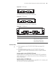
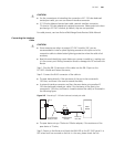
When connecting a switch to your router, a Bell V four-wire connection is
preferred.
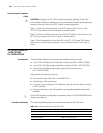
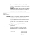
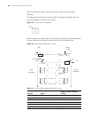
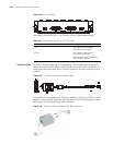
The following figure shows the pinouts of RJ-45 receptacle on E&M cards. The
pins are numbered 1 to 8 from left to right:
Figure 241 Pinouts of RJ-45 receptacle
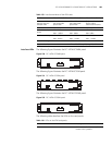
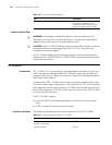
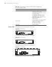
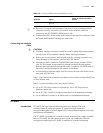
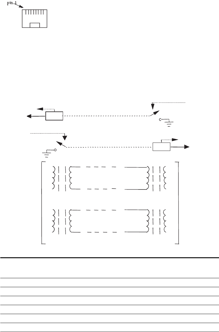
When connection is made in Bell V 4-wire mode, the pinouts of RJ-45 receptacles
at router side and at the switch side are shown in the following figure:
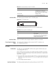
Figure 242 E&M interface cable (Bell V 4-wire)
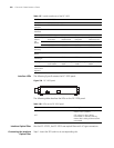
Table 141 Pinouts of E&M interface cable (Bell V 4-wire)
Router side
Signal at switch side (Bell V
4-wire) RJ-45 Pin Signal
1 SB (negative power supply) -
2 E M
3 RING0 RING0
4 RING1 RING1
5 TIP1 TIP1
6 TIP0 TIP0
7 M E
-48V
PBX
Router
detect
M
E
7
on-hook
off-hook
on-hook
-48V
on-hook
detect
M
E
2
off-hook
4- wire
6
T0
R0
T1
T1
R1 R1
R0
T0
4
5
3
4- wire
voice signal
-48V
voice signal