


72 CHAPTER 3: MULTIFUNCTIONAL INTERFACE MODULES
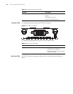
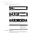
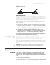
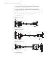
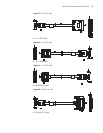
Interface LEDs MIM-1GEF panel is shown in the following figure:
Figure 70 MIM-1GEF panel
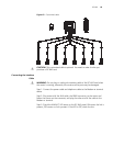
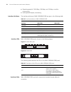
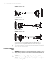
MIM-2GEF panel is shown in the following figure:
Figure 71 MIM-2GEF panel
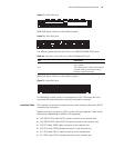
The following table describes the LEDs on the MIM-1GEF/MIM-2GEF panel.
Transm
itting
optical
power
Type Multi-m
ode
short-ha
ul (850
nm)
Single
mode
medium
-haul
(1310
nm)
Long-haul (1310 nm) Long-haul
(1550 nm)
Ultra-long (1550
nm)
Min. -9.5
dBm
-9 dBm -2 dBm -4 dBm -4 dBm
Max. 0 dBm -3 dBm 5 dBm 1 dBm 2 dBm
Receiver
sensitivity
-17 dBm -20 dBm -23 dBm -21 dBm -22 dBm
Central
wavelength
850 nm 1310
nm
1310 nm 1550 nm 1550 nm
Fiber type 62.5/12
5 μm
multi-m
ode
9/125
μm
single
mode
9/125 μm single mode 9/125 μm
single
mode
9/125 μm single
mode
Max.
transmission
segment
0.55 km
(0.34
mi.)
10 km
(6.21
mi.)
40 km (24.86 mi.) 40 km
(24.86
mi.)
70 km (43.50 mi.)
Operating
mode
1000 Mbps
Full duplex
Table 41 Interface attributes of MIM-1GEF/MIM-2GEF
Attribute
Description
MIM-1GEF MIM-2GEF