


140 CHAPTER 3: MULTIFUNCTIONAL INTERFACE MODULES
c
CAUTION: For a long-haul fiber-optic interface, the transmission distance must be
longer than 25 km (15.5 in.) to allow the receiver to work. In case of closer
distances, insert an optical attenuator to reduce the input optical power.
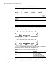
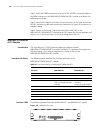
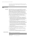
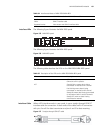
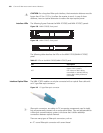
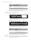
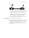
Interface LEDs The following figures illustrate the MIM-1CPOS(E) and MIM-1CPOS(T) panels:
Figure 159 MIM-1CPOS(E) front panel
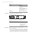
Figure 160 MIM-1CPOS(T) front panel
The following table describes the LEDs on the MIM-1CPOS(E)/MIM-1CPOS(T)
panel.
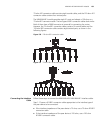
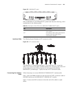
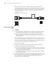
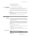
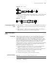
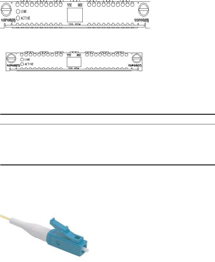
Interface Optical Fiber The MIM-1CPOS module can only be connected with an optical fiber cable with
an LC-type fiber-optic connector.
Figure 161 LC-type fiber-optic connector
n
Fiber-optic connectors, according to ITU, are passive components used to stably
but not permanently connect two or more optical fibers. They are indispensable to
a fiber-optic communications system in the sense that it allows add/drop
connections between optical channels.
There are many types of fiber-optic connectors, such as
■ FC: round fiber-optic connector with screw thread
Table 97 LEDs on the MIM-1CPOS(E)/MIM-1CPOS(T) panel
LED Description
LINK OFF means no link is present; ON
means a link is present.
ACT OFF means no data is being
transmitted or received; blinking
means data is being received or
transmitted.