


206 CHAPTER 4: FLEXIBLE INTERFACE CARDS
Connecting the Interface
Cable
c
CAUTION:
■ Some measures are taken to protect FIC-1VE1 module. Still, you are
recommended to install a special lightning arrester at the input end of its
connection cable to obtain better lightning protection when the cable is led
outdoors;
■ Read the mark identifying a port before you connect a cable to it, making sure
it is the correct port. Wrong connection tends to damage the MIM and even
the Router.
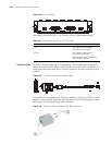
Step 1: Plug the DB-15 connector of the cable into the DB-15 port on the
FIC-1VE1 module and fasten the screws;
Step 2: Connect the RJ-45 connector of the cable to:
■ The peer device directly, if the resistance of the port to be connected is
120-ohm, and there is no need to extend the cable;
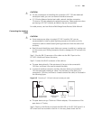
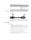
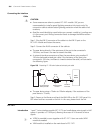
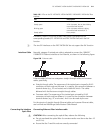
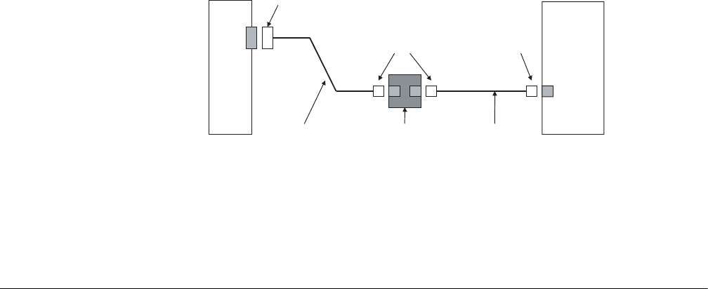
■ A network interface connector and then the peer device using another E1
120-ohm balanced twisted pair cable, if the resistance of the port to be
connected is 120-ohm, and there is a need to extend the cable, as illustrated in
the following figure.
Figure 253 Extending E1 120-ohm balanced twisted pair cable
■ The peer device using a 75ohm-to-120ohm adapter, if the resistance of the
peer device is 75-ohm;
Step 3: Power on the Router and check the LINK LED on the FIC-1VE1 panel. It is
OFF when fault has occurred on the link. In this case, please check the link.
FIC-1VT1
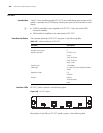
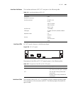
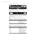
Introduction 1-port T1 voice interface module (FIC-1VT1) can handle dense voice signals in VoIP
system. It provides a CT1/PRI port, allowing the access of 24 channels of voice
signals.
n
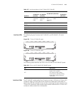
■ VCPM is provided to users together with FIC-1VT1. Users can select VPM
module as needed.
■ VPM module is installed on the main board of FIC-1VT1.
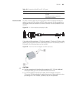
Router
Voice
Device
DB-15
Network interface
RJ-45
RJ-45
120-ohm balanced
120-ohm E1
trunk cable
twisted pair cable
connector