


MIM-2FXS/MIM-2FXO/MIM-2E&M and MIM-4FXS/MIM-4FXO/MIM-4E&M 115
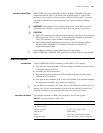
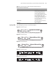
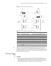
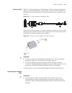
Figure 131 E&M interface cable (Bell V 4-wire)
n
Because it is hard to determine the type of the switch to be connected and its
connectors, interface cables of MIM-2E&M/MIM-4E&M modules have to be
prepared according to the on-spot conditions or by the user. To ensure the EMC of
the Router, install a ferrite core near the connector of the prepared E&M module
interface cable by the router side.
Connecting the Interface
Cable
c
CAUTION:
■ Some measures are taken to protect MIM-2FXS/MIM-2FXO/MIM-2E&M and
MIM-4FXS/MIM-4FXO/MIM-4E&M. Still, you are recommended to install a
special lightning arrester at the input end of each connection cable to obtain
better lightning protection effect when the cable is led outdoors;
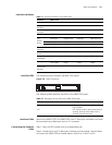
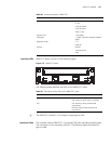
Table 75 Pinouts of E&M interface cable (Bell V 4-wire)
Router side
Signal at switch side (Bell V 4-wire) RJ-45 Pin RJ-45 interface signal
1 SB (negative power supply) -
2 E M
3 RING0 RING0
4 RING1 RING1
5 TIP1 TIP1
6 TIP0 TIP0
7 M E
8 SG (negative power supply
ground)
-
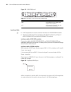
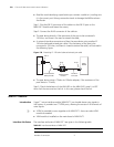
-48V
PBX
Router
detect
M
E
7
on-hook
off-hook
on-hook
-48V
on-hook
detect
M
E
2
off-hook
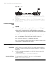
4- wire
6
T0
R0
T1
T1
R1 R1
R0
T0
4
5
3
4- wire
voice signal
-48V
voice signal