


MIM-1E1/MIM-2E1/MIM-4E1/MIM-1E1-F/MIM-2E1-F/MIM-4E1-F Modules 81
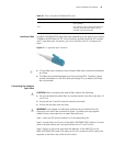
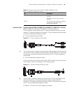
■ Dumb terminal cable
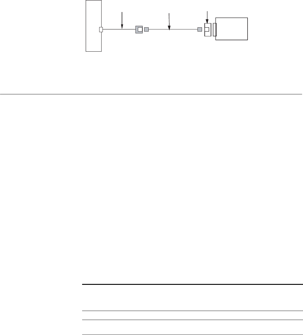
Connect the RJ-45 connector (female) to a standard network cable and then to a
dumb terminal adapter;
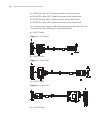
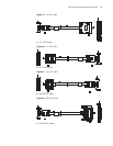
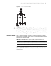
Figure 88 Connecting MIM-8ASE/MIM-16ASE cable to a dumb terminal
Step 3: Check the behavior of the LINK LED on the MIM-8ASE/MIM-16ASE panel.
It is OFF when fault has occurred on the link and signal is out of synchronization.
In this case, please check the link.
MIM-1E1/MIM-2E1/MI
M-4E1/MIM-1E1-F/MI
M-2E1-F/MIM-4E1-F
Modules
Introduction MIM-1E1/MIM-2E1/MIM-4E1
MIM-1E1/MIM-2E1/MIM-4E1, the 1-/2-/4-port channelized E1/PRI interface
module, transmits, receives, and processes E1 data traffic. In addition, you can use
the card for other purposes, such as CE1 access and the ISDN PRI function.
MIM-1E1-F/MIM-2E1-F/MIM-4E1-F
The MIM-1E1-F/MIM-2E1-F/MIM-4E1-F module is different from the
MIM-1E1/MIM-2E1/MIM-4E1 module in the sense that:
■ The FE1 operating mode supported by the E1-F cards allows only one n × 64
kbps bundle to be formed on each interface, where n = 1 to 31. However, an
E1 card allows arbitrary grouping of 31 channels and multiple bundles.
■ The E1-F modules do not support PRI mode.
Interface Attributes The interface attributes of MIM-1E1/MIM-2E1/MIM-4E1 and
MIM-1E1-F/MIM-2E1-F/MIM-4E1-F are given in the following table:
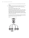
Standard
network cable
Dumb
adapter
Dumb terminal adapter
8ASE/16ASE dumb
terminal cable
Router
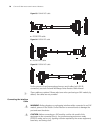
Standard
network cable
Dumb
adapter
Dumb terminal adapter
8ASE/16ASE dumb
terminal cable
Router
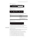
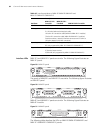
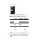
Table 46 Interface attributes of MIM-1E1/MIM-2E1/MIM-4E1 and
MIM-1E1-F/MIM-2E1-F/MIM-4E1-F
Attribute
Description
MIM-1E1/1E1-
F module
MIM-2E1/2E1-
F module MIM-4E1/4E1-F module
Connector DB-15 DB-15 DB-25
Number of
connectors
1 2 1
Interface standard G.703, G.704