


SIC-1VE1 47
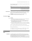
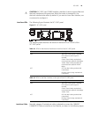
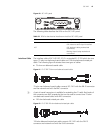
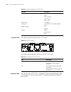
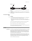
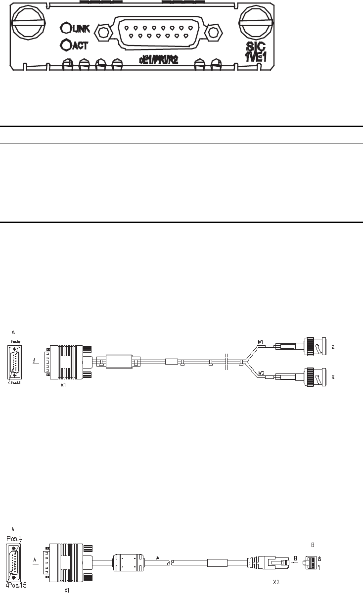
Figure 40 SIC-1VE1 panel
The following table describes the LEDs on the SIC-1VE1 panel.
Interface Cable The interface cable of SIC-1VE1/SIC-1E1-F is a standard E1 G.703 which has two
types: 75-ohm non-balanced coaxial cable and 120-ohm balanced twisted pair
cable. The following figure illustrates these two types of cables.
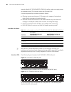
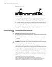
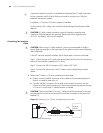
■ 75-ohm non-balanced coaxial cable
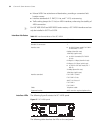
Figure 41 E1 G.703 75-ohm non-balanced coaxial cable
75-ohm non-balanced coaxial cable connects SIC-1VE1 with the DB-15 connector
and the network end with the BNC connector.
n
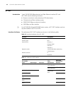
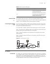
A pair of coaxial connectors is available for extending the E1 cable. Both ends of
the connectors are BNC receptacles that can be used to connect two 75-ohm
non-balanced coaxial cables with BNC connectors.
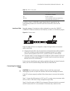
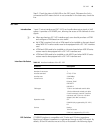
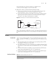
■ 120-ohm balanced twisted pair cable
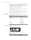
Figure 42 E1 G.703 120-ohm balanced twisted pair cable
120-ohm balanced twisted pair cable connects SIC-1VE1 with the DB-15
connector and network end with the RJ-45 connector.
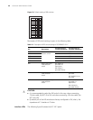
Table 22 LEDs for the electrical interface on the left of SIC-1GEC panel
LED Description
LINK ON means carrier signal is received;
OFF means no carrier signal is received.
ACT OFF: No data is being received and
transmitted;
Blinking: Data is being received and
transmitted.