


224 CHAPTER 4: FLEXIBLE INTERFACE CARDS
Step 2: Connect the cable.
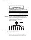
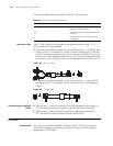
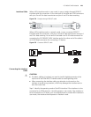
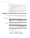
1 To connect the module to an ISDN network, identify the type of the ISDN line
provided by your telecommunications service provider.
■ If it is an ISDN U interface line, use an NT1 for conversion. Insert one end of the
S/T interface cable into the S/T interface on the NT1 and the other end to a BSV
interface on the FIC-2BSV/FIC-4BSV.
■ If it is an ISDN S/T interface line, directly connect the cable to a BSV interface on
the FIC-2BSV/FIC-4BSV.
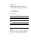
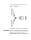
2 To connect the module to a TE device, use a crossover S/T interface cable. Connect
the RJ-45 plug at one end of the cable to the FIC-2BSV/FIC-4BSV interface, the
RJ-45 receptacle to a straight-through S/T interface cable, and then the
straight-through cable to the TE device.
FIC-24FXS
Introduction The 24-port voice subscriber circuit interface card (FIC-24FXS) processes and
transmits voice signals over data communications networks for 24 regular analog
phones, faxes, or AT0 loop trunks of telephone exchanges. It occupies two FIC
slots.
Interface Attributes
Interface LEDs FIC-24FXS has two kinds of LEDs, Active and Link.
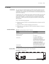
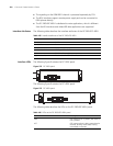
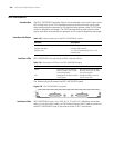
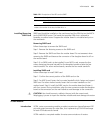
The following figure illustrates the FIC-24FXS panel.
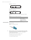
Figure 276 FIC-24FXS front panel
Table 167 Interface attributes of the FIC-24FXS card
Attribute Description
Connector 50-pin D-type female connector
Interface standard FXS interface
Interface rate 24 × FXS interface rate
Table 168 Description of LEDs on the FIC-24FXS panel
LED Description
Active OFF means all links are idle. Blinking means
one or more links are occupied.
Link Steady ON means no fault occurs on the
link