


178 CHAPTER 4: FLEXIBLE INTERFACE CARDS
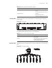
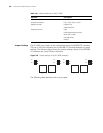
At one end of the cable is a DB-68 connector for connecting the router and at the
other end are eight RJ-45 connectors for connecting other devices.
Connecting the Interface
Cable
c
CAUTION: Before you connect a port, read its label carefully; a wrong connection
can impair the interface card and even damage the device.
If the interface cable is routed outdoors, you are recommended to install a special
lightning arrester at the input end of the interface cable for better lightning
protection.
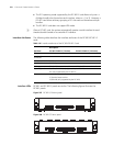
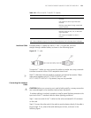
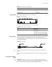
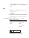
Step 1: Insert the DB-68 connector of the 8T1 conversion cable to the DB-68 port
on the FIC-8T1/FIC-8T1-F card.
Step 2: Connect one RJ-45 connector at the other end of the cable to the device
to be connected.
Step 3: Power on the router. Check the behavior of the LINK LED on the card
panel: OFF means fault occurs on the line. Check the line status.
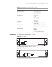
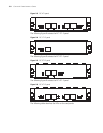
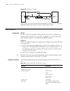
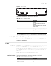
FIC-1CE3
Introduction FIC-1CE3, the 1-port channelized E3 interface card, delivers these functions:
■ In E3 mode, transmitting, receiving, and processing one channel of E3 fast
traffic; providing E3 traffic access.
■ In CE3 mode, providing the subscribers with N × 64 kbps low-speed access,
where N is smaller than or equal to 128.
n
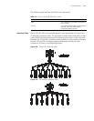
■ E3 represents the tertiary group rate of E system in the TDM system, that is,
34.368 Mbps. Through E23 and E12 demultiplexing, an E3 channel can be
channelized into 16 E1 lines, each supporting both the E1 and CE1 modes. E23
means either E2-to-E3 multiplex or E3-to-E2 demultiplex, and E12 means
E1-to-E2 multiplex or E2-to-E1 demultiplex. “E23” and “E12” discussed here
represent the demultiplex process.
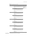
Interface Attributes The following table describes the interface attributes of the FIC-1CE3/FIC-2CE3.
Table 122 FIC-1CE3 interface attributes
Attribute Description
Connector SMB
Number of connectors 2
Interface standard G.703
G.704
G.751
Interface rate 34.368 Mbps
Cable type E3 cable (75-ohm coaxial cable)