


98 CHAPTER 3: MULTIFUNCTIONAL INTERFACE MODULES
Interface Cable The external interface provided by a MIM-1CE3 module is two SMB sockets
respectively for Tx (Transmitter end) and Rx (Receiver end). The interface adopts
75ohm unbalanced transmission mode and uses a pair of 75ohm unbalanced
coaxial cables to connect the peer device.
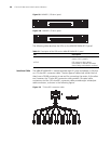
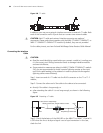
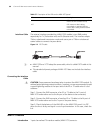
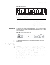
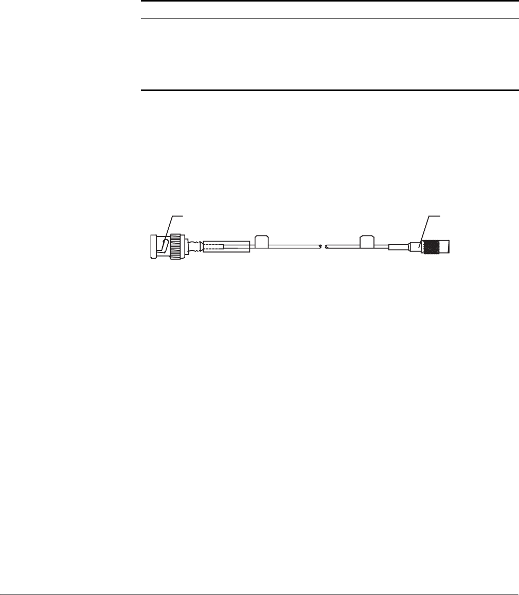
Figure 111 E3/T3 cable
n
■ MIM-1CE3 and 1CT3 adopt the same cable, which is called E3/T3 cable in this
manual.
■ The standard shipment package of MIM-1CE3 does not include the interface
cable.
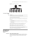
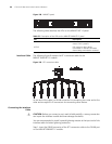
Connecting the Interface
Cable
c
CAUTION: Some measures have been taken to protect the MIM-1CE3 module. To
achieve better lightning protection effects, however, you are recommended to add
a special lightning arrester at the input end of the E3 or T3 cable when it is led
outdoors.
Step 1: Connect the SMB connector of an E3 or T3 cable to the Tx port of
MIM-1CE3 and another end to the Rx port of the device to be connected;
Step 2: Connect the SMB connector of another E3 or T3 cable to the Rx port of
MIM-1CE3 and another end to the Tx port of the peer device;
Step 3: Check the behavior of the LINK LED on the MIM-1CE3 panel. It is OFF
when the line is faulty and signal is out of synchronization. In this case, check the
link.
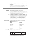
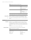
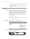
MIM-1CT3 Module
Introduction 1-port channelized T3 interface module (MIM-1CT3) serves to:
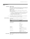
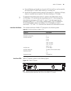
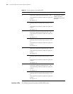
Table 57 Description of the LEDs on the MIM-1CE3 panel
LED Description
LINK OFF means the link is not set up. ON
means the link has been set up.
ACT OFF means no data is being
transmitted or received; blinking
means data is being received or/and
transmitted.
BNC connector SMB connectorBNC connector SMB connector