


138 CHAPTER 3: MULTIFUNCTIONAL INTERFACE MODULES
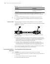
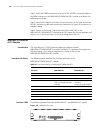
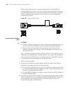
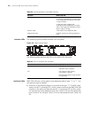
When a BSV interface works in network mode, it uses a crossover ISDN S/T
interface cable for connection, with pins 3 and 6 for data transmission and pins 4
and 5 for data receiving. At one end of the cable is an RJ-45 plug for connecting
the BSV interface and at the other end of the cable is an RJ-45 receptacle for
connecting a TE device.
Figure 158 Crossover ISDN S/T cable
Connecting the Interface
Cable
c
CAUTION:
■ If outdoor cabling is involved, you need to install a special lightning arrester at
the input end of the ISDN BRI S/T interface cable to avoid lightning strike.
■ When connecting the interface cable, pay attention to the mark on the
interface to avoid wrong insertion, which may damage the interface card or
even the router host.
Step 1: Identify the operating mode of the BSV interface. If the interface is to be
connected to an ISDN network, it should operate in user mode; if the interface is
to be connected to a TE device, such as a digital phone or another BSV interface in
user mode, the interface should operate in network mode.
Step 2: Connect the cable.
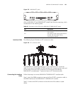
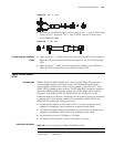
1 To connect the module to an ISDN network, identify the type of the ISDN line
provided by your telecommunications service provider.
■ If it is an ISDN U interface line, use an NT1 for conversion. Insert one end of the
S/T interface cable into the S/T interface on the NT1 and the other end to a BSV
interface on the MIM-2BSV/MIM-4BSV.
■ If it is an ISDN S/T interface line, directly connect the cable to a BSV interface on
the MIM-2BSV/MIM-4BSV.
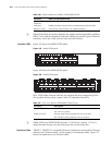
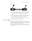
2 To connect the module to a TE device, use a crossover S/T interface cable. Connect
the RJ-45 plug at one end of the cable to the MIM-2BSV/MIM-4BSV interface, the
RJ-45 receptacle to the straight-through S/T interface cable, and then the
straight-through cable to the TE device.