


SIC-1TPRI/SIC-1T1-F 35
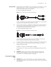
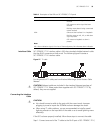
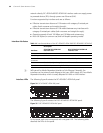
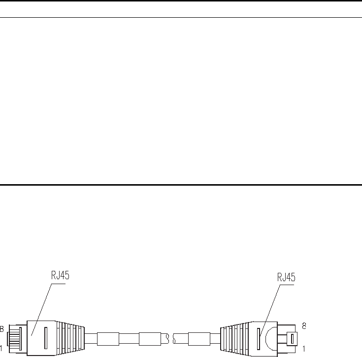
Interface Cable SIC-1TPRI/SIC-1T1-F interface cable is 100-ohm standard shielded network cable
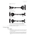
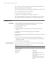
that has RJ-45 connectors at both ends. The following figure illustrates a
SIC-1TPRI/SIC-1T1-F interface cable:
Figure 27 T1 cable
For the pinouts of T1 cable, see Low-End and Mid-Range Series Routers Cable
Manual.
c
CAUTION: Relevant cables are included in the standard shipment package of
SIC-1TPRI/SIC-1T1-F. Please order them together with SIC-1TPRI/SIC-1T1-F. By
default, they are not supplied.
Connecting the Interface
Cable
c
CAUTION:
■ You should connect a cable to the port with the correct mark. Improper
plugging is prone to impair the SIC/MIM and even damage the router.
■ When using T1 cable outdoors, you are recommended to install a special
lightning arrester on the input end of the cable so as to avoid lightning more
effectively.
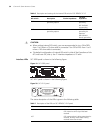
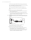
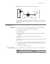
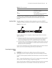
If the SIC has been properly installed, follow these steps to connect the cable:
Step 1: Connect one end of the T1 cable to the RJ-45 port of SIC-1TPRI/SIC-1T1-F;
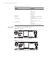
Table 9 Description of the LEDs on SIC-1TPRI/SIC-1T1-F panel
LED Description
LINK/ACT ON means the carrier signal has been
received.
OFF means no carrier signal has been
received.
Blinking means data is being transmitted
or/and received.
LP/AL ON means the interface is in a loopback.
Blinking means an AIS, LFA, or RAI alarm
signal is present.
OFF means no loopback or alarm is
present.
Note:
AIS = Alarm indication signal; LFA = loss of frame alignment; RAI = Remote alarm indication