


MIM-16FSW/MIM-16FSW-PoE/DMIM-24FSW/DMIM-24FSW-PoE 129
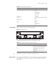
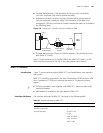
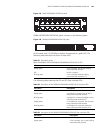
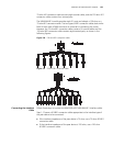
Figure 145 MIM-16FSW/MIM-16FSW-PoE panel
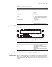
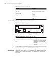
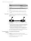
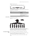
DMIM-24FSW/DMIM-24FSW-PoE panel is shown in the following figure:
Figure 146 DMIM-24FSW/DMIM-24FSW-PoE panel
On the panel, each 10/100 Mbps interface corresponds to a green LED. The
following table describes the status of these LEDs.
The following tables describe the GE and SFP fiber interface LEDs:
Table 87 Description of the
MIM-16FSW/MIM-16FSW-PoE/DMIM-24FSW/DMIM-24FSW-PoE FE LEDs
LED status Description
Steady green A link is present, but no data is being
transmitted and received.
OFF No link is present.
Blinking green A link is present and data is being
transmitted and received (ACT).
Table 88 Description of the DMIM-24FSW/DMIM-24FSW-PoE GE interface LEDs
LED status Description
OFF No link is present.
Steady green A gigabit link is present, but no data is
being transmitted and received.
Blinking green A gigabit link is present and data is being
transmitted and received (ACT).
Steady yellow A 100 Mbps link is present, but no data is
being transmitted and received.
Blinking yellow A 100 Mbps link is present and data is
being transmitted and received (ACT).
Table 89 Description of the DMIM-24FSW/DMIM-24FSW-PoE fiber interface LEDs
LED status Description
OFF No link is present.
Steady green A link is present, but no data is being
transmitted and received.