


FIC-1E1/FIC-2E1/FIC-4E1 and FIC-1E1-F/FIC-2E1-F/FIC-4E1-F 167
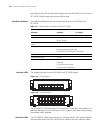
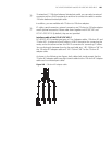
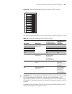
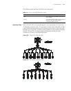
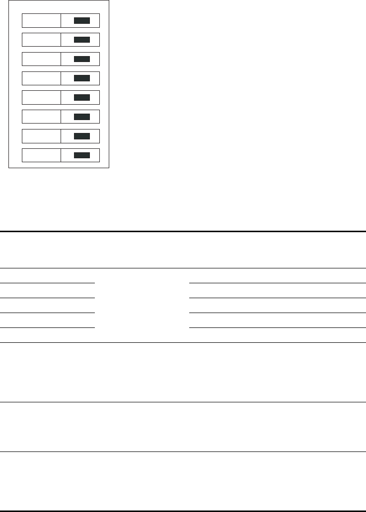
Figure 204 Default setting of the DIP switches for the FIC-E1/FIC-E1-F cards
The following table describes how to set a DIP switch on the FIC-E1/FIC-E1-F cards:
c
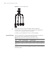
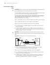
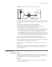
CAUTION: When connecting an FIC-E1/FIC-E1-F card to an external 75-ohm cable,
you are recommended to place BITs 1 through 8 to the ON position; when
connecting the card to an external 120-ohm cable, place BITs 1 through 8 to the
OFF position. Only trained personnel are allowed to change the settings of the DIP
switches.
By default, all the DIP switch BITs are in the ON position (factory default), which
means the impedance of E1 ports is 75-ohm.
Table 115 Setting DIP switches on the FIC-E1/FIC-E1-F cards
DIP switch Description
Configuration of
75-ohm impedance
Configuration of
120-ohm
impedance
1BIT 75-ohm/120-ohm
toggle switch
ON OFF
2BIT ON OFF
3BIT ON OFF
4BIT ON OFF
5BIT ON OFF
6BIT RxRing grounding
mode switch
OFF: RxRing is
grounded using
capacitance.
ON: RxRing is
grounded directly.
-
7BIT RxShield grounding
switch
- ON: RxShield is
grounded.
OFF: RxShield is not
grounded.
8BIT RxShield grounding
mode switch
- OFF: RxShield is
grounded using
capacitance
ON: RxShield is
grounded directly.
on
1
2
3
4
5
6
7
8