


Configuring Multiple Spanning Trees
22-15
22
Migration button to manually re-check the appropriate BPDU format (RSTP or
STP-compatible) to send on the selected interfaces. (Default: Disabled)
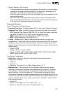
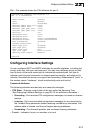
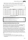
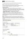
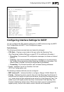
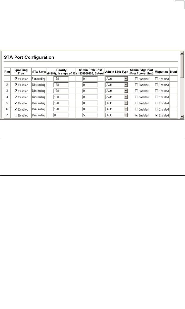
Web – Click Spanning Tree, STA, Port Configuration or Trunk Configuration. Modify
the required attributes, then click Apply.
Figure 22-4 STA Port Configuration
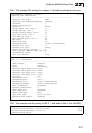
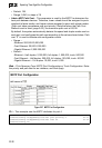
CLI – This example sets STA attributes for port 7.
Configuring Multiple Spanning Trees
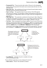
MSTP generates a unique spanning tree for each instance. This provides multiple
pathways across the network, thereby balancing the traffic load, preventing
wide-scale disruption when a bridge node in a single instance fails, and allowing for
faster convergence of a new topology for the failed instance.
By default all VLANs are assigned to the Internal Spanning Tree (MST Instance 0)
that connects all bridges and LANs within the MST region. This switch supports up
to 33 instances. You should try to group VLANs which cover the same general area
of your network. However, remember that you must configure all bridges within the
same MSTI Region (page 22-8) with the same set of instances, and the same
instance (on each bridge) with the same set of VLANs. Also, note that RSTP treats
each MSTI region as a single node, connecting all regions to the Common Spanning
Tree.
To use multiple spanning trees:
1. Set the spanning tree type to MSTP (STA Configuration, page 22-6).
2. Enter the spanning tree priority for the selected MST instance (MSTP VLAN
Configuration).
Console(config)#interface ethernet 1/7 45-1
Console(config-if)#no spanning-tree spanning-disabled 51-11
Console(config-if)#spanning-tree port-priority 0 51-13
Console(config-if)#spanning-tree cost 50 51-12
Console(config-if)#spanning-tree link-type auto 51-15
Console(config-if)#no spanning-tree edge-port 51-13
Console(config-if)#spanning-tree protocol-migration 51-17