Hardware
100 Megabit Modem 400F, 500L, 600F, and 700F User Manual
HARDWARE
The following provides additional information about Megabit Modem 400F, 500L, 600F, and
700F such as the installation kit and modem connectors pinouts.
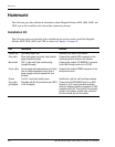
Installation Kit
The following items are included in the installation kit and are used to install the Megabit
Modem 400F, 500L, 600F, and 700F as shown in Chapter 3 on page 18.
Part Description Function
Rubber feet Four black rubber feet Attaches to the base of the modem.
Grey cable Silver-satin phone cord with 4-pin modular
plugs (straight-through)
Connects the modem ADSL connector to the
wall phone jack for access to the Internet.
Black cable CAT 5, cable with 8-pin modular plugs
(straight-through)
Connects the modem 10/100BASE-T connector
to the LAN through a hub or to a PC NIC.
Power cable Power supply with optional power cord (this
item is ordered dependent on the type of
power supply and cord required for your
location)
Connects the modem POWER connector to the
local power source.
Screws Two 6x
1
/
2
-inch sheet metal screws Installs into a wall for wall-mounting modems.
Grey cable
and adapter
Flat cable with RJ-45 connectors and a DB-9
to RJ-45 adapter.
Connects the RS-232 MGMT port to an ASCII
terminal or a PC running terminal emulation
software. Adapter assembly connects to a DB-9
connector on the PC. Then, one RJ-45 connector
installs in the adapter and the other connector
into the console port on the modem.


