


Managing CMM Directory Content CMM Files
OmniSwitch 6600 Family Switch Management Guide March 2005 page 4-9
Redundancy
CMM software redundancy is one of the switch’s most important fail over features. For CMM software
redundancy, at least two fully-operational OmniSwitches must be linked together as a stack. In addition,
the CMM software must be synchronized. (Refer to “Synchronizing the Primary and Secondary CMMs”
on page 4-26 for more information.)
When two OmniSwitches are running in a stack, one switch has the primary role and one switch has the
secondary role at any given time. (The primary and secondary roles are determined by the switch number
indicated on the LED on the front panel; the lowest number switch becomes the primary switch in the
stack.) The primary switch manages the current switch operations while the secondary switch provides
backup (also referred to as “fail over”).
Additional OmniSwitches in a stack are set to “idle” for the purposes of redundancy. For more informa-
tion on managing a stack of switches, see “Managing Stacks” in the OmniSwitch 6600 Family Hardware
Users Guide.
Note. A redundant stacking cable is required to fully support redundancy.
Redundancy Scenarios
The following scenarios demonstrate how the CMM software is propagated to other switches in a stack for
the purposes of coherent redundancy. In the examples below W represents the working directory and C
represents the certified directory.
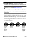
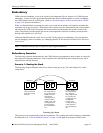
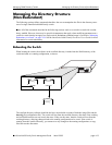
Scenario 1: Booting the Stack
The following diagram illustrates what occurs when a stack powers up. The stack displayed is a three
switch stack.
Powering Up a Stack
This process occurs automatically when the switch boots. The working and certified directory relationship
described above in “Software Rollback Feature” on page 4-4 still apply to the primary CMM switch.
WC
WC
WC
1. Stack is pow-
ered up and boots
from the certified
directory.
2. The contents of
the certified direc-
tory of the primary
CMM switch are
copied to the
working directory
of the secondary
CMM switch. The
working directory
is then copied to
the certified direc-
tory.
3. The contents of
the certified direc-
tory of the pri-
mary CMM switch
are copied to the
working directory
of additional
switches. The
working directory
is then copied to
the certified direc-
tory.
Switch #1 Switch #2 Switch #3