


x610 Series Layer 3 Gigabit Ethernet Switches Installation Guide
103
Power Wiring to a DC AT-PWR250 Power Supply Module
To power on a switch with a DC AT-PWR250 Power Supply Module,
perform the following procedure:
Warning
As a safety precaution, install a circuit breaker with a minimum value
of 15 Amps between the equipment and the DC power source.
E9
Warning
Always connect the wires to the LAN equipment first before you
connect the wires to the circuit breaker. Do not work with HOT feeds
to avoid the danger of physical injury from electrical shock. Always
be sure that the circuit breaker is in the OFF position before
connecting the wires to the breaker.
E9
Warning
For centralized DC power connection, install only in a restricted
access area.
E23
Note
A tray cable is required to connect the power source if the unit is
powered by centralized DC power. The tray cable must be a UL
listed Type TC tray cable and rated at 600 V and 90 degrees C, with
three conductors, minimum 14 AWG.
E24
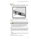
1. Power off the DC circuit to be used for the chassis.
2. Verify that the On/Off switch on the DC AT-PWR250 Module is in the
Off position.
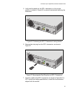
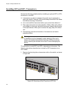
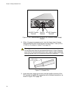
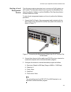
3. Use the legend above the terminal block to identify the terminals. The
terminals are positive, power supply ground and negative, from left
to right, as shown in Figure 71 on page 104.