


x610 Series Layer 3 Gigabit Ethernet Switches Installation Guide
45
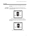
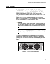
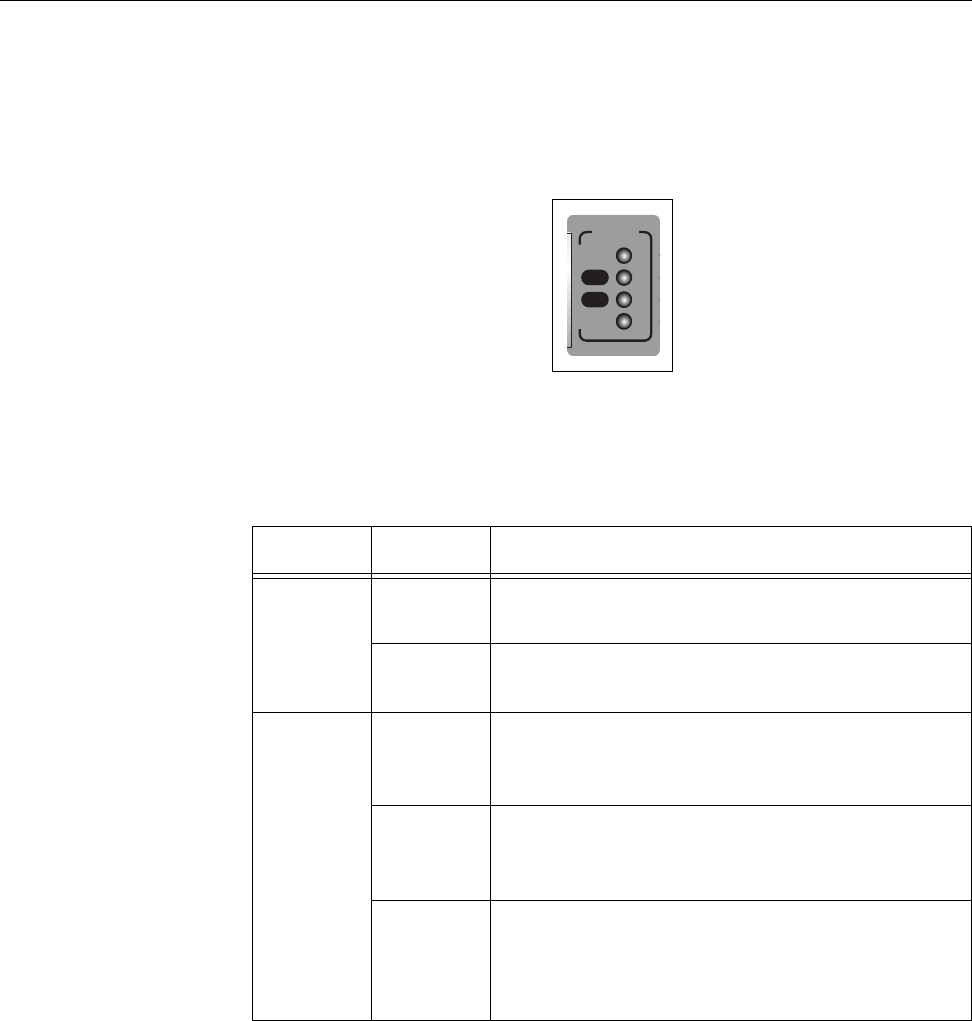
STACK LEDs
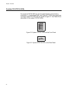
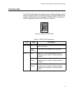
The STACK LEDs display the link status of the VCStack stacking module
and its two stacking ports. If a stacking module or the stack cables are not
installed, all LEDs remain off. To locate the STACK LEDs, see Figure 22,
and for a description of the STACK LEDs, see Table 10.
PRES
MSTR
L/A
L/A
1
2
STACK
Figure 22. Switch STACK LEDs
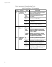
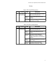
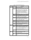
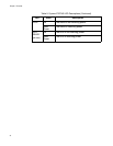
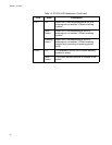
Table 10. STACK LED Descriptions
LED State Description
MSTR Off The switch is not part of a stack or is a member
un
it of the stack.
Solid
Gre
en
The switch is the master unit of the stack.
L/A 1 Off Stack Port 1 has not established a link to a
st
acking port on another VCStack stacking
module.
Solid
Gre
en
Stack Port 1 has established a link to a
stacking port on another VCStack stacking
module.
Flashing
Gre
en
Stack Port 1 has established a link to a
stacking port on another VCStack stacking
module and is sending or receiving packet
traffic.