


x610 Series Layer 3 Gigabit Ethernet Switches Installation Guide
53
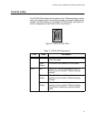
AT-LBM (Loop Back) Module
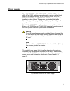
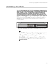
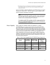
The x610-48Ts/X and x610-48Ts/X-POE+ switches are shipped from the
factory with an AT-LBM module installed in the expansion slot on the rear
panel, as shown in Figure 29. This module is factory installed for the
non-stacking configuration. It provides the capability for a full line rate,
non
-blocking switching configuration when there are connections on the
x610-48Ts/X and x610-48Ts/X-POE+ switches to all 44 copper ports, two
SFP ports, and two SFP+ ports. If you need to configure the switch for
stacking, you may install a VCStack stacking module in place of the
AT-LBM Module.
POWER SUPPLY
RPS
READY
RPS INPUT
56V/18A MAX 12V/21A MAX
STACKING
WARNING
This unit may have more than one power input. To reduce the risk of
electric shock, disconnect both A/C and RPS inputs before servicing
unit.
AT-L BM
Figure 29. AT-LBM Module Installed in x610-48Ts/X Expansion Slot
Note
The AT-LBM module is very similar to a blank panel in its outward
appearance except that it is marked with the “AT_LBM” model name
in the upper left-hand corner of the faceplate.
If the AT-LBM module is replaced with either an AT-StackXG or
AT-x6EM/XS2 stacking module, the switching configuration is no
longer non-blocking.