


x610 Series Layer 3 Gigabit Ethernet Switches Installation Guide
51
Redundant Power Supplies
The Redundant Power Supply connector on an x610 Series switch rear
panel can connect to an optional Redundant Power Supply (RPS), the
AT-RPS3000. The RPS can provide power to the switch in the event of a
failure
of the switch’s internal power supply.
The AT-RPS3000 has slots for two power supply modules. Either the
AT-PWR800 (800W) or AT-PWR1200 (1200W) power supply modules
can be
installed in the RPS.
Warning
Do not hot swap the power supply modules. It is not necessary to
power down the RPS before you remove or swap a power supply
module. However, always disconnect the AC cord before the power
supply module is removed and ensure the power supply module is
correctly installed before reconnecting the AC cord.
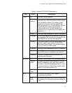
When fully populated, the RPS can support up to four x610 switches
simultaneously, depending on the switches configuration. The RPS can
backup one high-power consumption switch or two low-power
consumption switches with each power supply module. The 24 port
switches are considered low-power consumption switches while the 48
port switches are considered high-power consumption switches. The RPS
is not able to identify if the attached switch is a high-power consumption
switch or a low-power consumption switch.
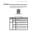
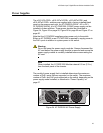
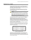
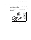
The RPS has four connectors on the rear panel, as shown in Figure 28.
Connectors 1 and 2 supply power from power supply module A, the right
side module, an
d connectors 3 and 4 supply power from power supply
module B, the left side module.
Figure 28. Connectors on RPS
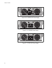
Connectors 1 and 3 supply system power only and connectors 2 and 4
supply syste
m power and extra PoE power. A switch connected to
connector 2 will receive extra PoE power only from power supply module
A and a switch connected to connector 4 will receive extra PoE power only
from power supply module B.