


RPS
READY
STACKING
risk of
rvicing
AT-LX44CPUCVR
Chapter 3: Installing the Hardware
90
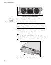
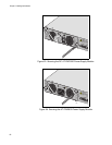
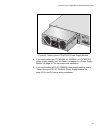
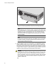
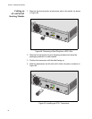
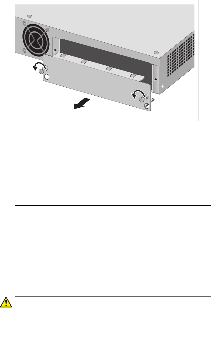
Figure 58. Removing the Blank Panel from the Expansion Slot
Note
All x610 Series Layer 3 Switch models, except the x610-48Ts/X and
x610-48Ts/X-POE+, are shipped from the factory with a blank panel
installed in the rear panel expansion slot. The x610-48Ts/X and
x610-48Ts/X-POE+ are shipped from the factory with an AT-LBM
module installed.
Note
Do not remove the blank panel from the chassis until you are ready
to install a module. An open slot allows dust to enter the unit and
reduces proper airflow and cooling.
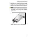
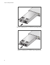
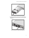
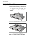
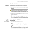
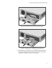
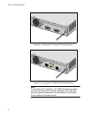
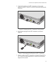
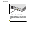
3. Align the edges of either the AT-StackXG or AT-x6EM/XS2 stacking
module with the guides in the slot and carefully slide the module into
the chassis until it is flush with the rear panel of the chassis, as shown
in Figure 59 and Figure 60. Light pressure may be needed to seat the
module on the connector on the rear panel of the chassis.
Caution
Do not force the VCStack stacking module into place. Doing so may
damage the connector pins on the backplane inside the chassis. If
there is resistance, remove the module and reinsert it after verifying
that the edges of the card are properly aligned in the guides in the
chassis’ module slot.