


x610 Series Layer 3 Gigabit Ethernet Switches Installation Guide
49
Power Supplies
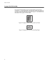
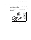
The x610-24Ts-POE+, x610-24Ts/X-POE+, x610-48Ts-POE+ and
x610-48Ts/X-POE+ switches are supplied with
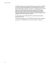
a factory installed blank
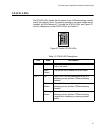
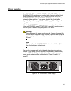
panel on the power supply slot. An AT-PWR250 (250W - AC or DC),
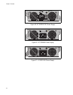
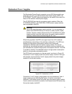
AT-PWR800 (800W), or a AT-PWR1200 (1200W) power supply can be
installed in these switches. These power supplies are illustrated in
Figure 24, Figure 25 on page 50, Figure 26 on page 50 and Figure 27 on
page 50.
Note that the AT-PWR250 supplies system power only to the switch.
Eith
er an AT-PWR800 or an AT-PWR1200 is required to supply power to
the PoE+ ports in addition to system power to the switch.
Warning
Do not hot swap the power supply modules. Always disconnect the
AC cord before the power supply module is removed and ensure the
power supply module is correctly installed before reconnecting the
AC cord.
Note
When installed, the AT-PWR1200 Module extends 5.6 cm (2.2 in.)
from the back panel of the chassis.
The model of power supply that is installed determines the maximum
number of PoE+ ports that are supported on the switch. The maximum
number of PoE+ and PoE ports supported on the switch, depending on the
power supply model installed, is described in “Power Capacity” on
page 57.
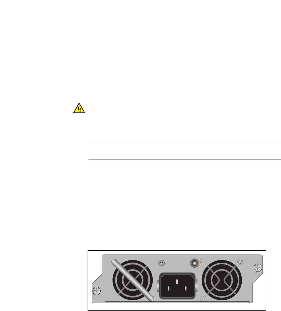
100-240VAC~ 5A MAX
DC PWR
FAULT
AT-PWR250
2196
Figure 24. AT-PWR250 AC Power Supply