


2205
A
A
AT-PWR250
DC OUT
FAU LT
+
-
6A
40-60VDC
FOR CENTRALIZED DC POWER
CONNECTION, INSTALL ONLY IN A
ON
OFF
+48 VDC Positive Ground -48 VDC Negative
TerminalTerminalTerminal
8mm ±1mm
(0.31in. ±0.039in.)
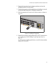
Chapter 4: Cabling the Network Ports
104
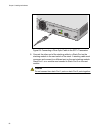
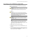
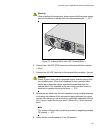
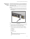
Figure 71. DC Terminal Block on the DC AT-PWR250 Power Supply
Module
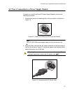
4. With a 14-gauge wire-stripping tool, strip the three wires in the tray
cable coming from the DC input power source to 8mm ± 1mm (0.31 in.,
± 0.039 in.), as shown in Figure 72 on page 104.
Warning
Do not strip more than the recommended amount of wire. Stripping
more than the recommended amount can create a safety hazard by
leaving exposed wire on the terminal block after installation. E10
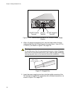
Figure 72. Stripped Wire
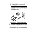
5. Insert the power supply ground wire into the middle connector of the
DC terminal and tighten the connection with a flathead screwdriver, as
shown in Figure 73 on page 105.