


x610 Series Layer 3 Gigabit Ethernet Switches Installation Guide
67
Connecting
switches into a
stack
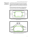
The proprietary high-speed communication protocol that is used over the
stacking links requires multiple twisted pairs and a high level of shielding.
This means that to stack x610 switches, specialized cables and
connections are required.
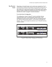
VCStack Stacking Modules, Cables, and Connections
The stacks are connected via the stacking ports on the VCStack stacking
modules, which are installed in the back of each switch. There are two
VCStack stacking modules available:
The AT-StackXG, which has two full-duplex, 12 Gbps stacking ports
The AT-x6EM/XS2, which has two 10 Gbps SFP+ stacking slots
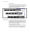
The following cables are used to connect the stacking ports when using
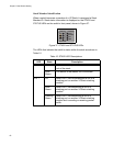
L/A 2 Off Stack Port 2 has not established a link to a
stacking port on another VCStack stacking
module.
Solid
Green
Stack Port 2 has established a link to a
stacking port on another VCStack stacking
module.
Flashing
Green
Stack Port 2 has established a link to a
stacking port on another VCStack stacking
module and is sending or receiving packet
traffic.
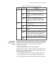
PRES Off The expansion slot for the VCStack stacking
module is empty.
Solid
Green
A VCStack stacking module is installed in the
switch.
MASTER Off Indicates that the switch is not the Stack
Master.
Flashing
Green
Indicates the specific stack member’s ID of the
switch in response to the ‘show stack indicator’
command. The LED will repeatedly flash ‘n’
times in quick succession, followed by a longer
pause, where n is the stack member's ID.
Solid
Green
Indicates that the switch is the STACK Master.
Table 16. STACK LED Descriptions (Continued)
LED State Description